Service Entities
Page 42 7210 SAS-X, R6 OS Services Guide
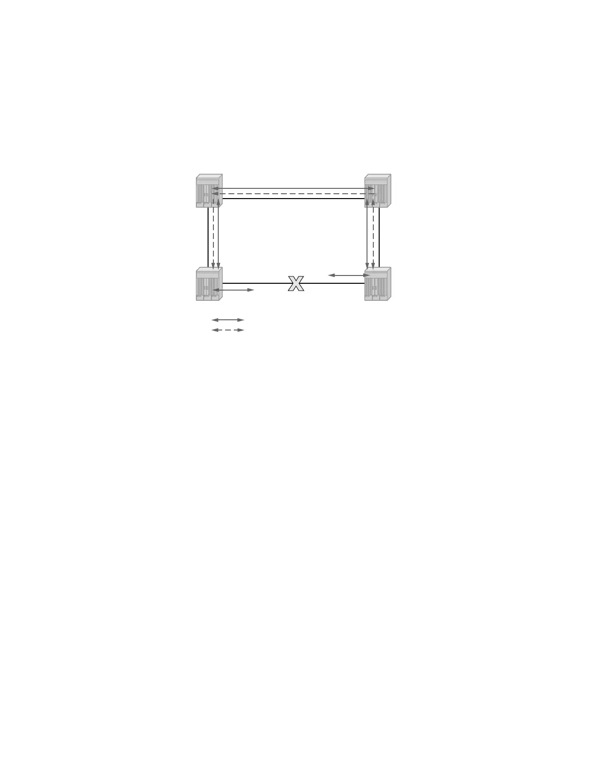
nodes for the affected service instances. The ring is now in protecting state and full ring
connectivity is restored. MAC learning takes place to allow Layer 2 packet forwarding on a ring.
The following picture depicts the failed link scenario.
Figure 7: 0-1 G.8032 Ring in the Protecting State
Once the failed link recovers, the nodes that blocked the link again send the R-APS messages
indicating no failure this time. This in turn triggers RPL Owner to block the RPL link and indicate
the Blocked RPL link the ring in R-APS message, which when received by the nodes at the
recovered link cause them to unblock that link and restore connectivity (again all nodes in the ring
perform FDB Flush and MAC learning takes place). The ring is back in the normal (or idle) state.
Within each path, Y.1731 Maintenance Entity Group (MEG) Endpoints (MEPs) are used to
exchange R-APS specific information (specifically to co-ordinate switchovers) as well as
optionally fast Continuity Check Messages (CCM) providing an inherent fault detection
mechanism as part of the protocol. Failure detection of a ring path by one of the mechanisms
triggers to activate the protection links. Upon failure, re-convergence times are a dependent on the
failure detection mechanisms. In the case of Y.1731, the CCM transmit interval determines the
response time. The 7210 SAS device supports 100ms (millisecond) message timers that allows for
quicker restoration times. Alternatively, 802.3ah (Ethernet in the First Mile) or simple Loss of
Signal can act as a trigger for a protection switch where appropriate. In case of direct connectivity
between the nodes, there is no need to use Ethernet CC messaging for liveliness detection.
Revertive and non-revertive behaviors are supported. The Ring protection link (RPL) is
configured and Eth-rings can be configured to revert to the RPL upon recovery.
G.8032 supports multiple data channels (VIDs) or instances per ring control instance (R-APS tag).
G.8032 also supports multiple control instances such that each instance can support RPLs on
different links providing for a load balancing capability however once services have been assigned
to one instance the rest of the services that need to be interconnected to those services must be on
the same instance. In other words each data instance is a separate data VLAN on the same physical
Ring Link
Ring Link
Ring Link
Ring Link Unblocked
Ring APS - ERP - Control Channel
Ring Data Channel
7210
7210
7210
7210
Ring Node
Ring Node
Ring Node
“RPL Neighbor”
RPL Owner Node
OSSG480