17
Controls, Connectors, and Display
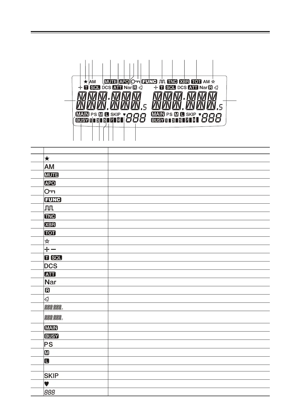
Display
①
⑫
⑬
⑭
⑮ ⑱
⑲
㉑ ㉒ ㉓ ㉔ ㉕ ㉖ ㉗ ㉘ ㉙
⑳
⑯⑰
② ③ ④ ⑤ ⑥ ⑦ ⑧ ⑨ ⑩ ⑪
No. Key Function
A
Appears when advanced set mode is available. (P.48)
B
Appears during AM reception. (P.36)
C
Appears during transmission when other band is set for mute. (P.52)
D
Appears when APO function is activated. (P.49)
E
Appears when setting the key lock. (P.62)
F
Appears when [FUNC] key is pressed. (P.15)
G
Appears when in the digital voice communication mode. (P.68)
H
Appears when in packet mode. (P.55)
I
Appears when cross-band repeater mode is available. (P.71)
J
Appears during time out timer setting. (P.49)
K
Appears during short cut setting. (P.63)
L
Appears when setting the shift. (P.22)
M
Appears when setting the tone squelch. (P.65)
N
Appears when setting the DCS. (P.66)
O
Appears when attenuator function is activated. (P.44)
P
Appears when in narrow band reception mode. (P.36)
g
Appears when reverse mode is activated. (P.32)
h
Appears when Bell function is activated. (P.39)
i
Indicates the VHF/UHF frequency or memory name on the left band side. (P.20, 28)
j
Indicates the VHF/UHF frequency or memory name on the right band side.
(P.20, 28)
k
Appears on the band with transmitting ability. (P.19)
l
Appears when a signal is being received. (P.31)
m
[S] Flashes during scan and [PS] flashes during program scan. (P.58)
n
Appears when transmission power is set to MID. (P.33)
o
Appears when transmission power is set to LOW. (P.33)
p
S meter Indicates received or transmitted signal level. (P.31, 32)
q
Appears during scan for skip channels. (P.59)
r
Appears when a favorite channel is selected. (P.59)
s
Indicates memory numbers in the memory mode. (P.23)