Publication 1756-UM523F-EN-P - December 2006
14 ControlLogix Redundancy System Overview
About the Main Parts of a
Redundant System
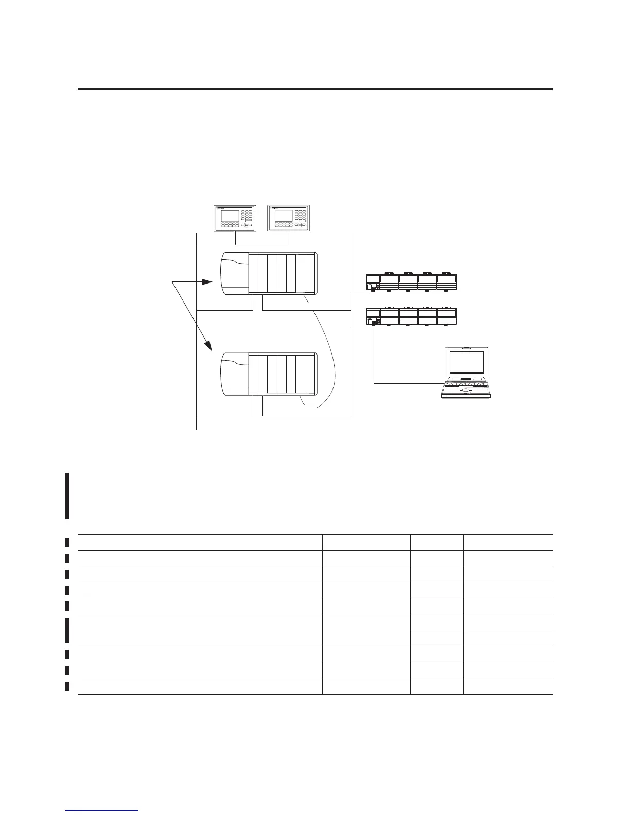
The ControlLogix redundancy system uses an identical pair of
ControlLogix chassis to keep a machine or process running if a
problem occurs with any hardware in one of the chassis.
This diagram illustrates the layout of a simple redundant setup.
ControlLogix Redundant System
Firmware Combinations
That Make Up a Redundant
System
These firmware combinations make up revisions 15.56 and 15.57 of
the ControlLogix redundancy system.
ControlLogix Redundancy Firmware Combinations
Identical Pair of
ControlLogix Chassis that
Controls a Machine or
Process
At Least 2 Other
ControlNet Nodes,
with Node Numbers
That are Lower Than
Those of the Two
1756-CNB Modules in
the Redundant Chassis
Network 2 - ControlNet Network for
I/O Communications
43128
Computer That is Connected to the
Network Access Port of a Remote Node
Network 1 -
EtherNet/IP Network or
ControlNet Network for HMI
Module Catalog Number Series Firmware Revision
ControlLogix5555 controller 1756-L55Mxx Any 15.57
ControlLogix5561 controller 1756-L61 Any 15.56
ControlLogix5562 controller 1756-L62 Any 15.56
ControlLogix5563 controller 1756-L63 Any 15.56
ControlNet bridge module 1756-CNB
1756-CNBR
D7.12
E 11.002
1756 10/100 Mbps EtherNet/IP Bridge, Twisted Pair Media 1756-ENBT Any 4.3
1756 10/100 Mbps EtherNet/IP Bridge w/ Enhanced Web Services 1756-EWEB Any 4.3
Redundancy module 1757-SRM Any 4.3

 Loading...


