Publication 1756-UM523F-EN-P - December 2006
30 Design the System
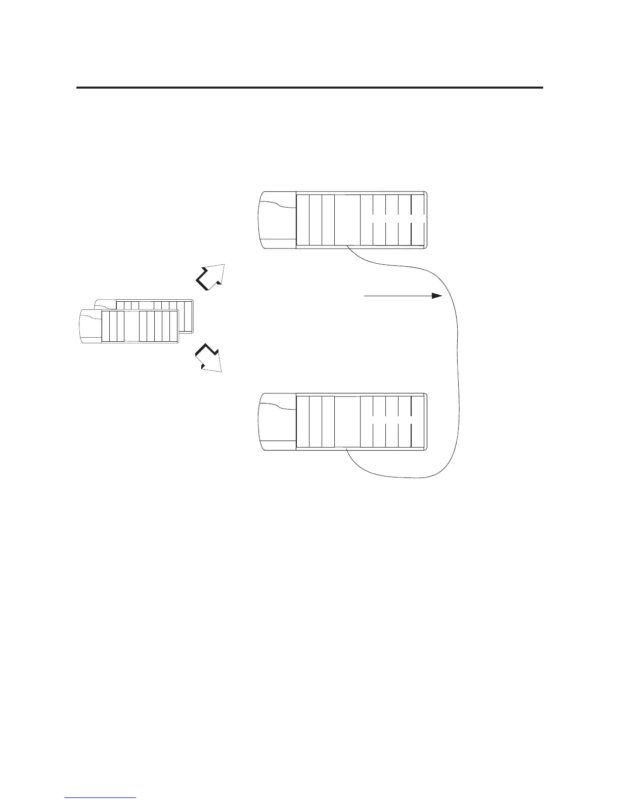
Placement of a Pair of
Redundant Chassis
With the standard redundancy module cables, a pair of redundant
chassis (primary and secondary) can function up to 100 m (300 ft)
apart.
Redundant Chassis Placement
If You Need More Than 100 Meters Between Chassis
To place the primary and secondary controller chassis more than 100
meters apart, use a custom fiber optic cable. For a custom cable,
follow these rules:
• Keep total light loss through the cable less than or equal to 7dB.
• Keep total length less than or equal to 4 km.
• Use high quality 62.5/125 micron multi-mode fiber-optic cable.
• Use professionally installed SC-style connectors to connect to
the 1757-SRM modules.
Redundancy Module Cable:
• 1757-SRC1 cable - 1 m (3 ft)
• 1757-SRC3 cable - 3 m (9 ft)
• 1757-SRC10 cable - 10 m (30 ft)
• 1757-SRC50 cable - 50 m (150 ft)
• 1757-SRC100 cable - 100 m (300 ft)
L
•
•
•
E
N
B
T
S
R
M
Redundant
Chassis A
Redundant
Chassis B
No Other Modules
C
N
B
L
•
•
•
E
N
B
T
S
R
M
No Other Modules
C
N
B

 Loading...


