Publication 1756-UM523F-EN-P - December 2006
Install the System 45
Repeated electrical arcing causes excessive wear to contacts on both a
module and its mating connector. Worn contacts may create electrical
resistance that can affect module operation.
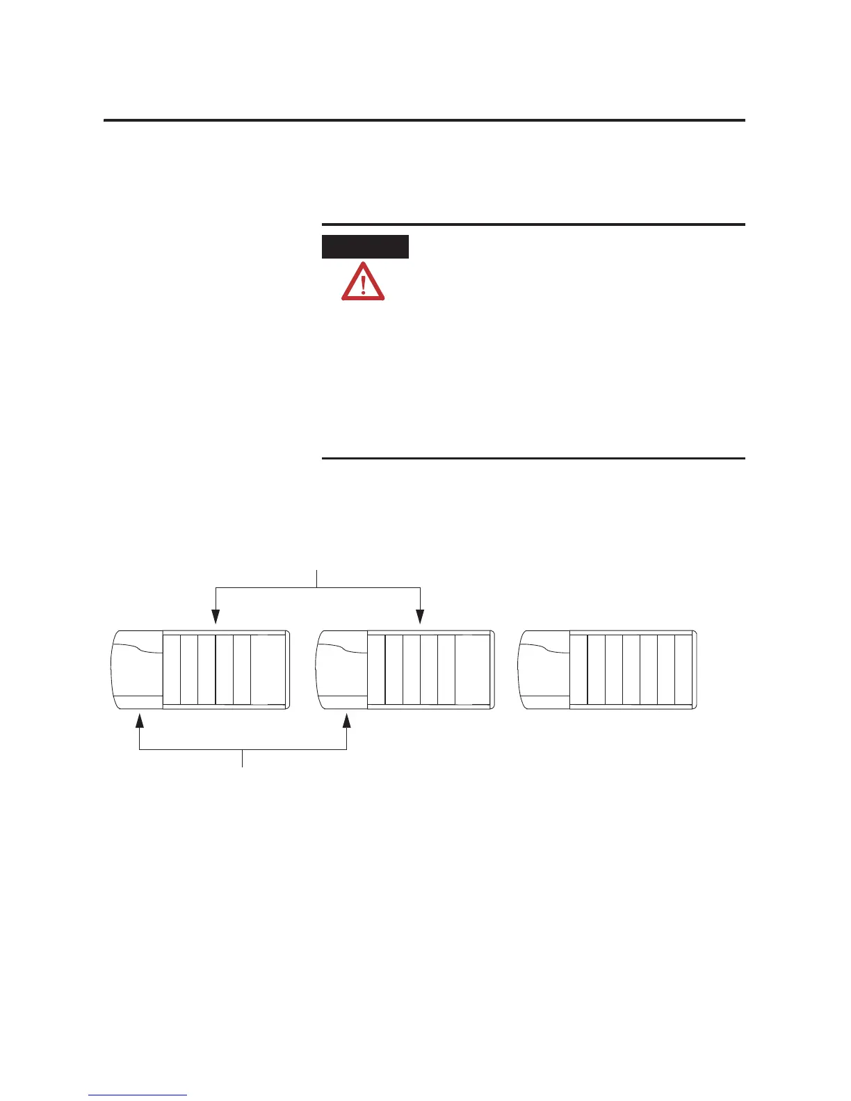
Install the Chassis for the
Controllers
1. Install the two ControlLogix chassis (redundant) that will contain
the controllers.
• Place the chassis within the length of a 1757-SRCx cable.
• Install each chassis according to the ControlLogix Chassis
Installation Instructions, publication 1756-IN080.
• If you are converting an existing system that contains local
I/O modules, you still need two additional chassis. In a
redundant system, you must place all I/O modules outside
the redundant chassis pair.
ATTENTION
Preventing Electrostatic Discharge
This equipment is sensitive to electrostatic discharge, which
can cause internal damage and affect normal operation. Follow
these guidelines when you handle this equipment:
• Touch a grounded object to discharge potential static.
• Wear an approved grounding wriststrap.
• Do not touch connectors or pins on component boards.
• Do not touch circuit components inside the equipment.
• If available, use a static-safe workstation.
• When not in use, store the equipment in appropriate
static-safe packaging.
1.
42798
2.

 Loading...


