Publication 1756-UM523F-EN-P - December 2006
46 Install the System
2. For each chassis, install a ControlLogix power supply according
to the corresponding installation instructions.
Install Modules in the First
Redundant Chassis
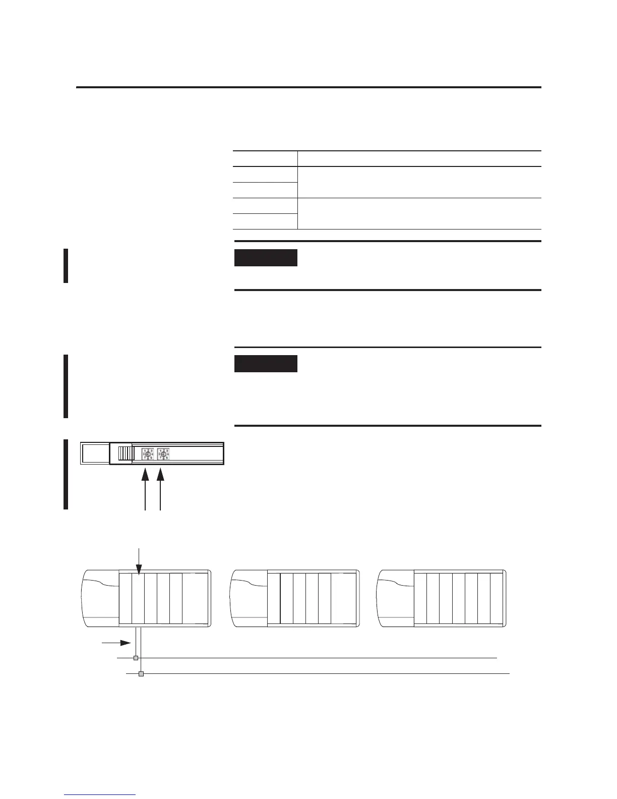
1. Set the rotary switches of each of the 1756-CNB/D/E or
1756-CNBR/D/E modules to the primary node number plus one.
For example, modules 3 and 4 have a primary node number of
2. If you allocate nodes 3 and 4 for the redundant chassis, set
both CNB modules to node 3.
Power Supply Publication
1756-PA72 ControlLogix Power Supplies Installation Instructions, publication
1756-IN078B
1756-PB72
1756-PA75R ControlLogix Redundant Power Supply Installation Instructions,
publication 1756-IN573C
1756-PB75R
IMPORTANT
We recommend constant power supply to one of the redundant
chassis to maintain uninterrupted operation of the redundant
controller parts.
IMPORTANT
Set the rotary switches of the 1756-CNB/D/E or
1756-CNBR/D/E modules for both redundant chassis to the
same node address.
The primary node number is the node number of the primary
chassis.
42796
Nodes 3 and 4
2.
3.
C
N
B
This is only an example. You can install the
module in any slot.

 Loading...


