Publication 1756-UM523F-EN-P - December 2006
Design the System 35
Checking Connection
Requirements
Set aside seven connections in each redundant controller for
redundancy communication.
• Two connections for the SRM
• Five connections for the partner controller
Planning a ControlNet
Network
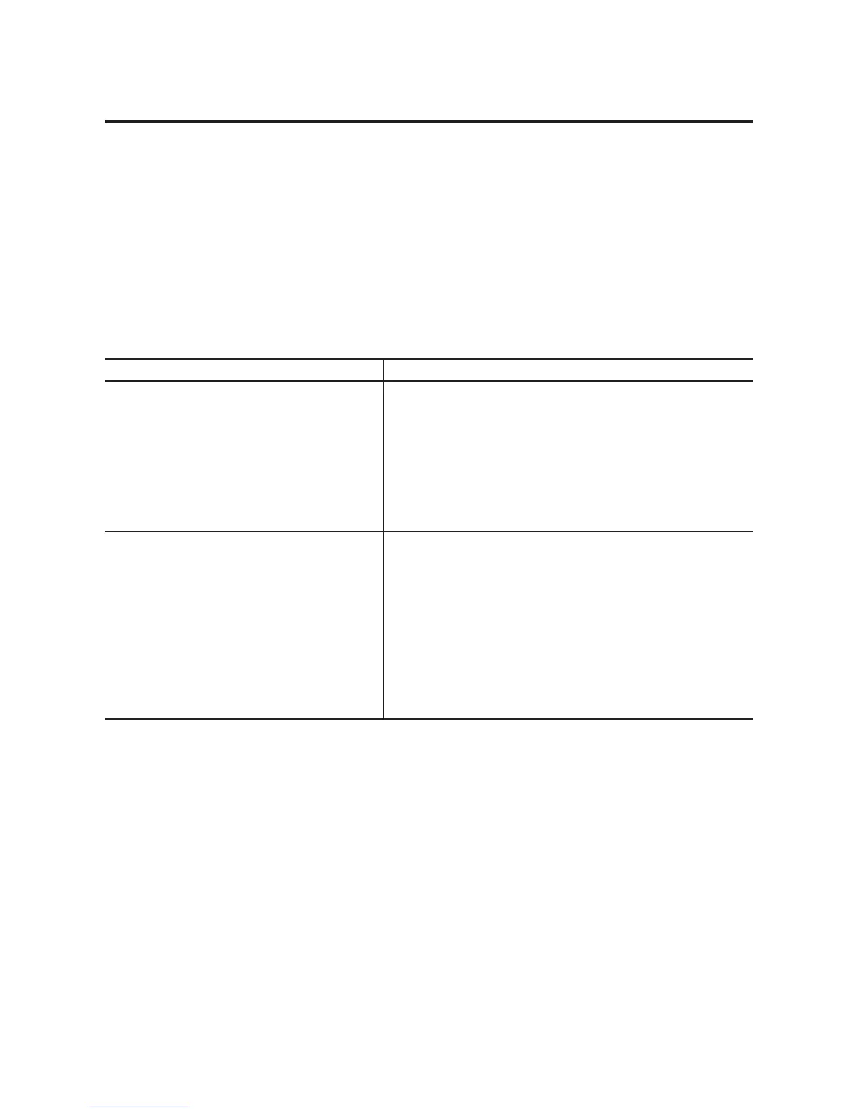
Follow these guidelines to plan a ControlNet network.
ControlNet Network Guidelines
Guideline Details
Make sure the network has at least 2 nodes plus the
redundant chassis pair.
An additional node can be:
• a second CNB module in the same remote chassis or in a different remote
chassis.
• any other ControlNet device.
• a workstation that is running RSLinx software.
If your ControlNet network contains only one node other than the redundant
chassis pair, that node will drop its connections during a switchover. This may
cause the outputs of that node to change state during the switchover.
Give the lowest ControlNet addresses to I/O chassis and
other remote chassis.
Do not give the lowest addresses to the redundant chassis pair.
If you give the lowest address to a CNB module in the redundant chassis pair:
• on a switchover, you may temporarily lose communication with I/O
modules, produced tags, and consumed tags.
• If you remove the CNB module from the primary chassis while chassis
power is on, you may temporarily lose communication with I/O modules,
produced tags, and consumed tags.
• If every ControlNet node powers down at the same time (for example, a
plant-wide power loss), you may have to cycle the power to the primary
chassis to restore communication.

 Loading...


