Publication 1762-UM001D-EN-P - March 2004
Specifications A-11
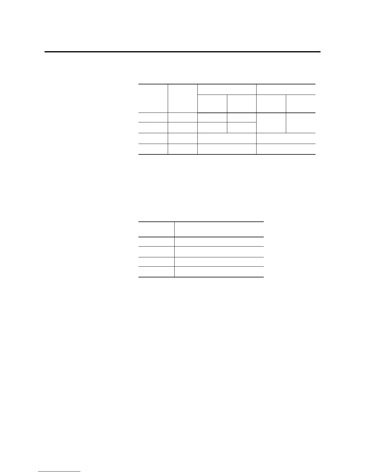
Table A.16 Relay Contact Ratings 1762-OX6I
Volts
(max.)
Continuous
Amps per
Point
(max.)
(1)
(1) The continuous current per module must be limited so the module power does not exceed 1440VA.
Amperes
(3)
(3) Surge Suppression – Connecting surge suppressors across your external inductive load will extend the
life of the relay contacts. For additional details, refer to Industrial Automation Wiring and Grounding
Guidelines, publication 1770-4.1.
Voltamperes
Make Break Make Break
240V ac 5.0 A 15 A 1.5 A 3600 VA 360 VA
120V ac
7.0 A
(2)
(2) 6 A in ambient temperatures above 40°C.
30 A 3.0 A
125V dc 2.5 A 0.4 A
50 VA
(4)
(4) DC Make/Break Voltamperes must be limited to 50 VA for DC voltages between 28V dc and 125V dc. DC
Make/Break Voltamperes below 28V dc are limited by the 7 A Make/Break current limit.
24V dc
7.0 A
(2)
7.0 A
168 VA
(4)
Table A.17 Module Load Ratings 1762-OX6I
Volts (max.) Controlled Load (Current) per Module
(max.)
240V ac 6 A
120V ac
12 A
(1)
(1) Current per relay limited to 6 A at ambient temperatures above 40°C.
125V dc 11.5 A
24V dc
30 A
(2)
(2) 24 A in ambient temperatures above 40°C. Limited by ambient temperature
and the number of relays controlling loads. See below.

 Loading...


