EasyManuals Logo

Allen-Bradley MicroLogix 1200 User Manual

Allen-Bradley MicroLogix 1200
162 pages
To Next Page IconTo Next Page
To Previous Page IconTo Previous Page
Page #48 background imageLoading...
Page #48 background image
Publication 1762-UM001D-EN-P - March 2004
3-12 Wiring Your Controller
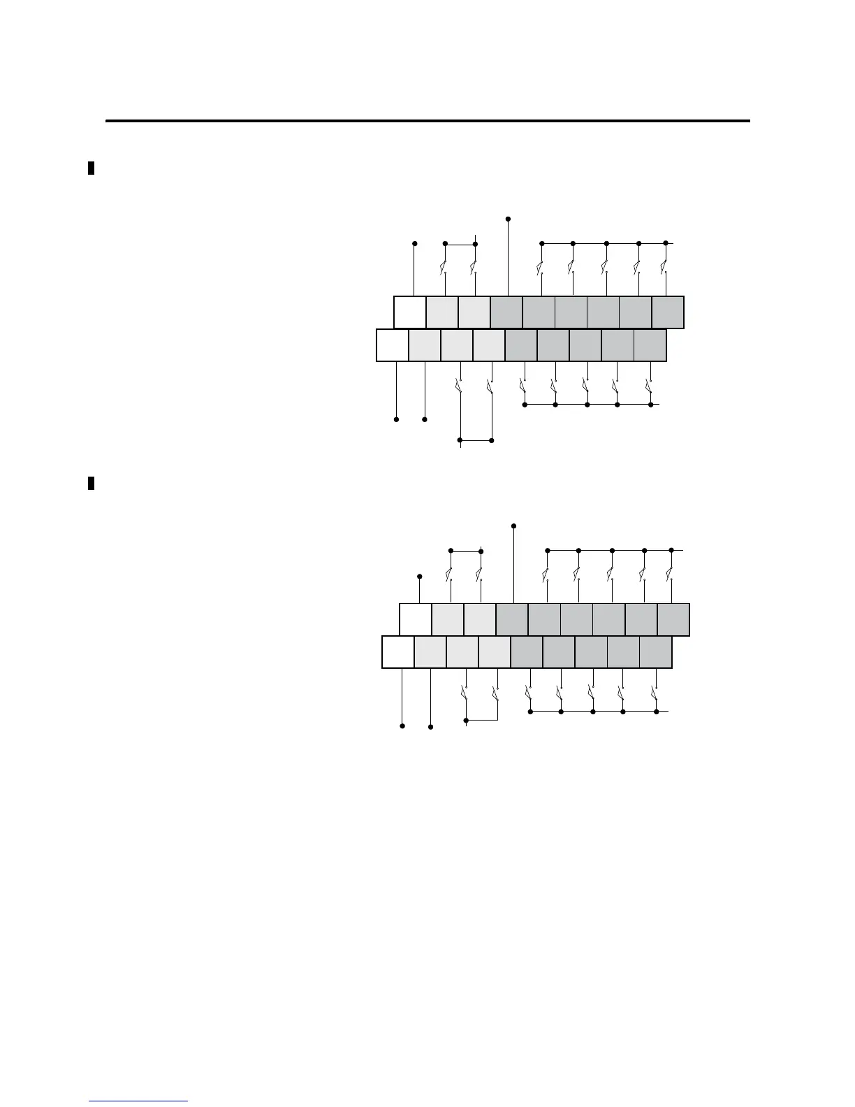
Figure 3.8 1762-L24BWA and 1762-L24BWAR Sinking Input Wiring Diagram
Figure 3.9 1762-L24BWA and 1762-L24BWAR Sourcing Input Wiring Diagram
+24
VDC
24
COM
IN 0 IN 2 IN 5 IN 7 IN 9
COM 1
IN 11 IN 13
COM 0
IN 1 IN 3 IN 4 IN 6 IN 8 IN 10 IN 12
-DCb
+DCb
+DCb
+DCa
+DCa
+DC
-DCa-DC
+24
VDC
24
COM
IN 0 IN 2 IN 5 IN 7 IN 9
COM 1
IN 11 IN 13
COM 0
IN 1 IN 3 IN 4 IN 6 IN 8 IN 10 IN 12
-DCb
-DC +DCa
-DCb
+DCb
+DC
-DCa
-DCa
24V dc Sensor Power

Table of Contents

Other manuals for Allen-Bradley MicroLogix 1200

Questions and Answers:

Question and Answer IconNeed help?

Do you have a question about the Allen-Bradley MicroLogix 1200 and is the answer not in the manual?

Allen-Bradley MicroLogix 1200 Specifications

General IconGeneral
SeriesMicroLogix 1200
TypeProgrammable Logic Controller (PLC)
MountingDIN rail or panel mount
Programming LanguageLadder Logic
Programming SoftwareRSLogix 500
I/O PointsUp to 40
Communication PortsRS-232, RS-485
Memory6 KB user memory
Power Supply24V DC or 120/240V AC
ExpansionSupports expansion I/O modules
Operating Temperature0°C to 55°C (32°F to 131°F)
Dimensions90 mm x 110 mm
Weight0.5 kg (1.1 lbs)

Related product manuals