Publication 1762-UM001D-EN-P - March 2004
A-2 Specifications
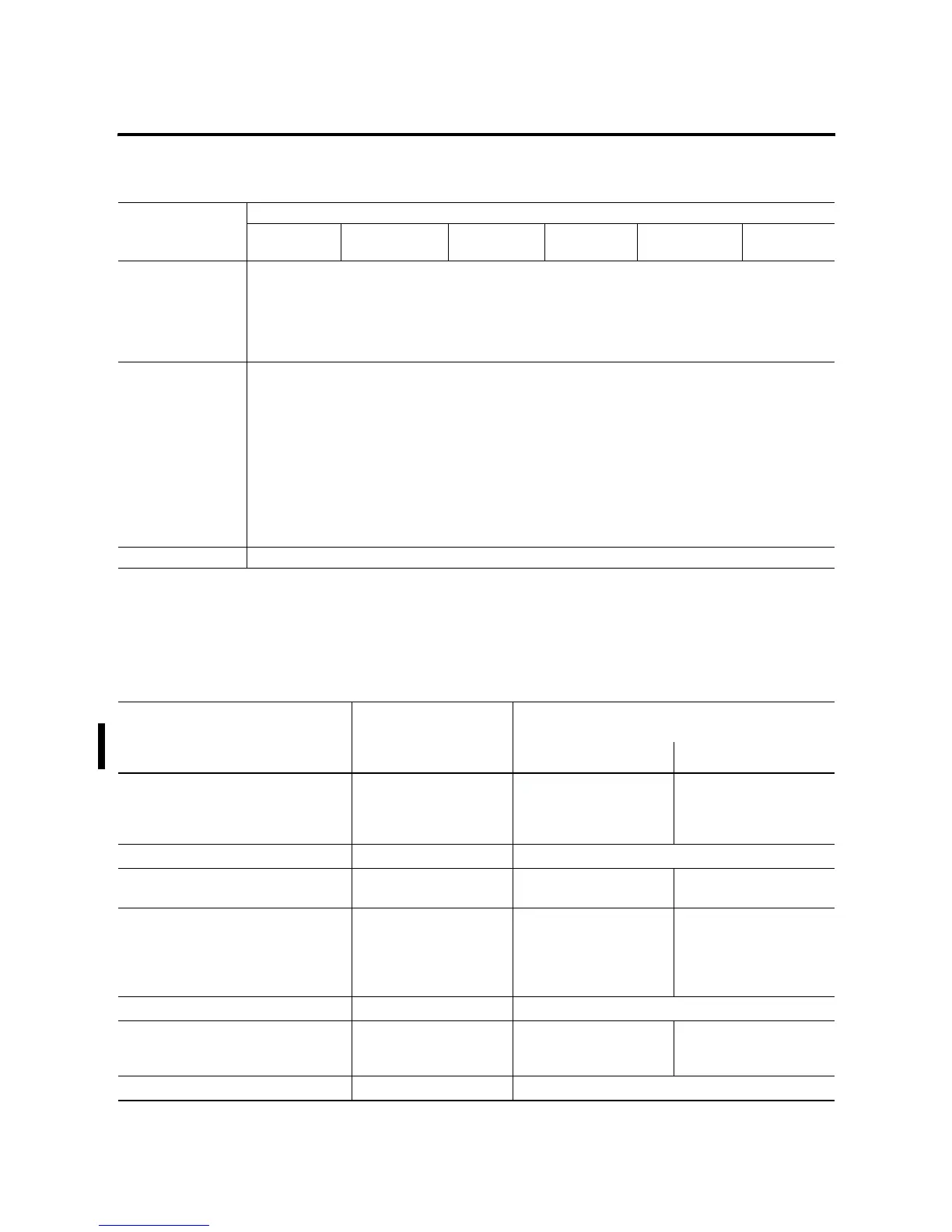
Agency Certification • UL 508
• C-UL under CSA C22.2 no. 142
• Class I, Div. 2, Groups A, B, C, D
(UL 1604, C-UL under CSA C22.2 no. 213)
• CE/C-Tick compliant for all applicable directives/acts
Electrical/EMC The controller has passed testing at the following levels:
• EN 61000-4-2: 4 kV contact, 8 kV air, 4 kV indirect
• EN 61000-4-3: 10V/m, 80 to 1000 MHz, 80% amplitude modulation, +900 MHz keyed carrier
• EN 61000-4-4: 2 kV, 5 kHz; communications cable: 1 kV, 5 kHz
• EN 61000-4-5: communications cable 1 kV galvanic gun
I/O: 2 kV CM (common mode), 1 kV DM (differential mode)
AC Power Supply: 4 kV CM (common mode), 2 kV DM (differential mode)
DC Power Supply: 500V CM (common mode), 500V DM (differential mode)
• EN 61000-4-6: 10V, communications cable 3V
Terminal Screw Torque 0.79
1 Nm (7 in-lb)
rated
(1) Do not allow the total load power consumed by the 5V dc, 24V dc, and sensor power outputs to exceed 12W.
(2) Do not allow the total load power consumed by the 5V dc, 24V dc, and sensor power outputs to exceed 16W.
See Appendix F for system validation worksheets.
Table A.1 General Specifications
Description 1762-
L24AWA
L24AWAR
L24BWA
L24BWAR
L24BXB
L24BXBR
L40AWA
L40AWAR
L40BWA
L40BWAR
L40BXB
L40BXBR
Table A.2 Input Specifications
Description 1762-L24AWA
1762-L40AWA
1762-L24AWAR
1762-L40AWAR
1762-L24BWA, -L24BXB, -L40BWA, -L40BXB
1762-L24BWAR, -L24BXBR, -L40BWAR, -L40BXBR
Inputs 0 through 3 Inputs 4 and higher
On-State Voltage Range 79 to 132V ac 14 to 24V dc
(+10% at 55°C/131°F)
(+25% at 30°C/86°F)
10 to 24V dc
(+10% at 55°C/131°F)
(+25% at 30°C/86°F)
Off-State Voltage Range 0 to 20V ac 0 to 5V dc
Operating Frequency 47 Hz to 63 Hz 0 Hz to 20 kHz 0 Hz to 1 kHz
(scan time dependent)
On-State Current:
•minimum
•nominal
•maximum
•5.0 mA at 79V ac
•12 mA at 120V ac
•16.0 mA at 132V ac
•2.5 mA at 14V dc
•7.3 mA at 24V dc
•12.0 mA at 30V dc
•2.0 mA at 10V dc
•8.9 mA at 24V dc
•12.0 mA at 30V dc
Off-State Leakage Current 2.5 mA max. 1.5 mA min.
Nominal Impedance 12KΩ at 50 Hz
10KΩ at 60 Hz
3.3KΩ 2.7KΩ
Inrush Current (max.) at 120V ac 250 mA Not Applicable

 Loading...


