Publication 1766-RM001A-EN-P - October 2008
Using the High-Speed Counter and Programmable Limit Switch 123
HSC Mode 7 - Quadrature Counter (phased inputs A and B) With External Reset
and Hold
Blank cells = don’t care, ⇑ = rising edge, ⇓ = falling edge
HSC Mode 8 - Quadrature X4 Counter
TIP
Inputs I1:0.0/0 through I1:0.0/11 are available for use as inputs to other
functions regardless of the HSC being used.
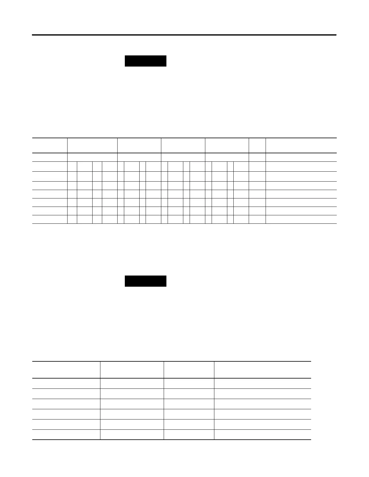
HSC Mode 7 Examples
Input
Terminals
I1:0.0/0 (HSC0) I1:0.0/1 (HSC0) I1:0.0/2 (HSC0) I1:0.0/3 (HSC0) CE
Bit
Comments
Function Count A Count B Z reset Hold
Example 1
(1)
⇑
off (0) off (0) on (1) HSC Accumulator + 1 count
Example 2
(2)
⇓ off (0) off (0) off (0) on (1) HSC Accumulator - 1 count
Example3 ⇓ off (0) off (0) on (1) Reset accumulator to zero
Example 4 on (1) Hold accumulator value
Example 5 on (1) Hold accumulator value
Example 6 off (0) on (1) Hold accumulator value
Example 7 off (0) off (0) Hold accumulator value
(1) Count input A leads count input B.
(2) Count input B leads count input A.
TIP
Inputs I1:0.0/0 through I1:0.0/11 are available for use as inputs to other
functions regardless of the HSC being used.
HSC Mode 8 Examples
I1:0.0/1(HSC0)
(A)
I1:0.0/1(HSC0)
(B)
Value of CE Bit Accumulator and Counter Action
▲ OFF TRUE Count Up Acc. Value
▲ ON TRUE Count Down Acc. Value
▼ OFF TRUE Count Down Acc. Value
▼ ON TRUE Count Up Acc. Value
OFF ▲ TRUE Count Down Acc. Value
ON ▲ TRUE Count Up Acc. Value
efesotomasyon.com - Allen Bradley,Rockwell,plc,servo,drive

 Loading...


