Publication 1766-RM001A-EN-P - October 2008
File Instructions 279
FFU - First In, First Out
(FIFO) Unload
Instruction Type: output
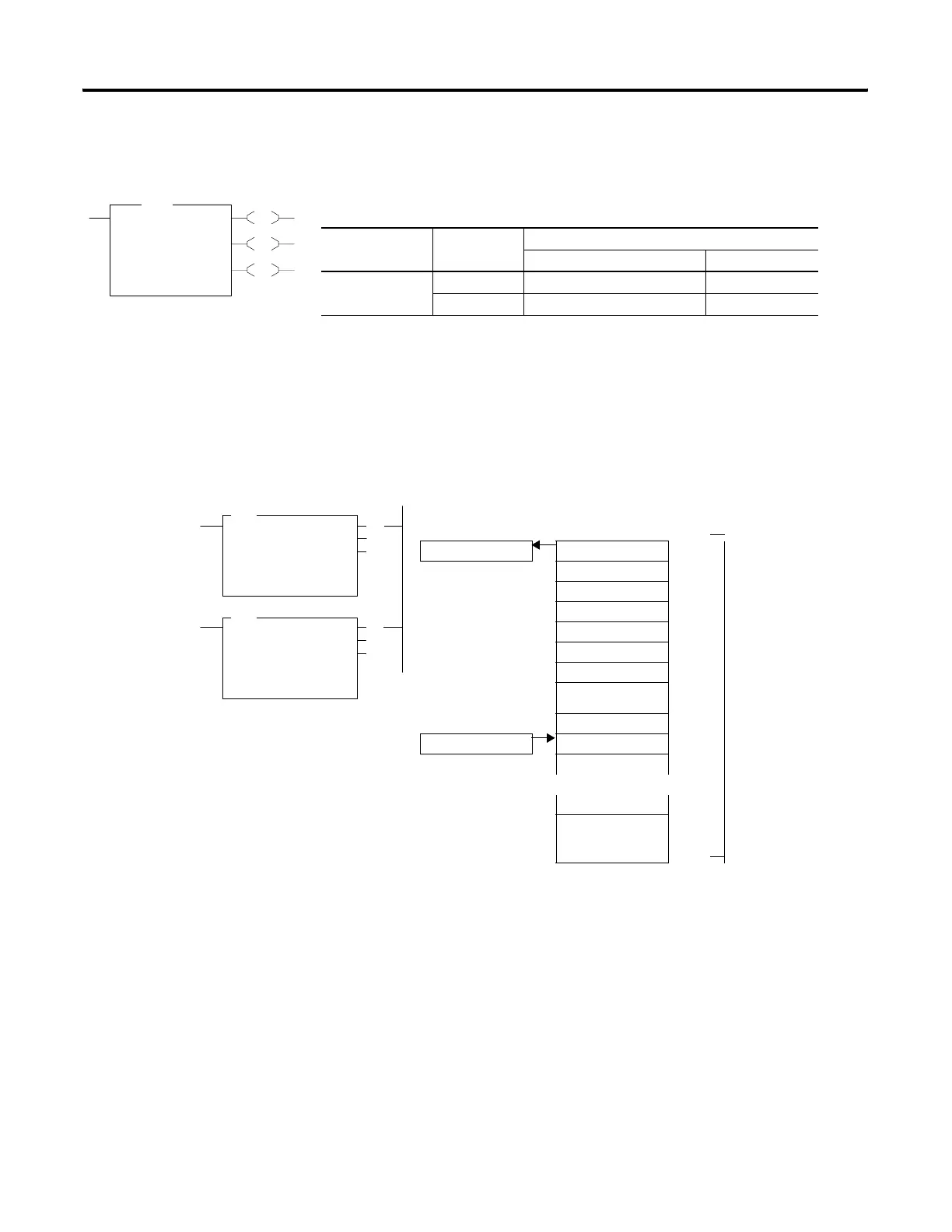
On a false-to-true rung transition, the FFU instruction unloads words or
long words from a user-created file called a FIFO stack. The data is
unloaded using first-in, first-out order. After the unload completes, the
data in the stack is shifted one element toward the top of the stack and
the last element is zeroed out. Instruction parameters have been
programmed in the FFL - FFU instruction pair shown below.
This instruction uses the following operands:
• FIFO - The FIFO operand is the starting address of the stack.
EU
DN
EM
FFU
FIFO Unload
FIFO #N7:0
Dest N7:1
Control R6:0
Length 1<
Position 0<
FFU
Execution Time for the FFU Instruction
Controller Data Size When Rung Is:
True False
MicroLogix 1400 word 8.7180 µs 6.6490 µs
long word 9.8890 µs 7.2150 µs
(EU)
(EM)
(DN)
FFL
FIFO LOAD
Source N7:10
FIFO #N7:12
Control R6:0
Length 34
Position 9
FFU
FIFO UNLOAD
FIFO #N7:12
Dest N7:11
Control R6:0
Length 34
Position 9
(EN)
(DN)
(EM)
Destination Position
N7:11 N7:12 0
N7:13 1
FFU instruction
unloads data from
stack #N7:12 at
position 0, N7:12
N7:14 2
3
4
5 34 words are allocated
for FIFO stack starting
at N7:12, ending at
N7:45
6
7
Source 8
N7:10 9
FFL instruction loads
data into stack
#N7:12 at the next
available position, 9
in this case.
N7:45 33
Loading and Unloading of Stack #N7:12
FFL and FFU Instruction Pair
efesotomasyon.com - Allen Bradley,Rockwell,plc,servo,drive

 Loading...


