EasyManuals Logo

Allen-Bradley MicroLogix 1400 User Manual

Allen-Bradley MicroLogix 1400
694 pages
To Next Page IconTo Next Page
To Previous Page IconTo Previous Page
Page #463 background imageLoading...
Page #463 background image
Publication 1766-RM001A-EN-P - October 2008
Communications Instructions 461
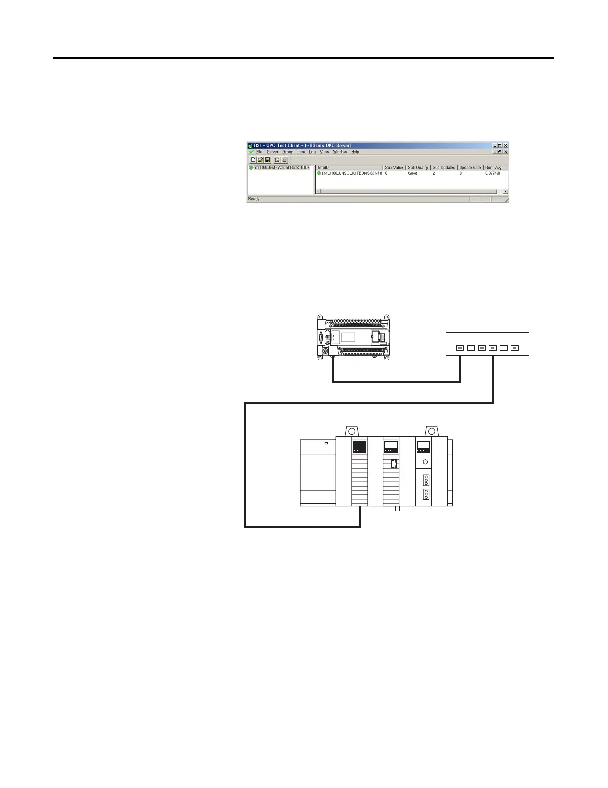
Trigger MSG instruction. It should complete done, and OPC Test
Client should display the N7:0 data, as well as “Good” Sub Quality:
Configuring a
MicroLogix 1400 CIP
Generic Message via
Ethernet
The MicroLogix 1400 supports CIP Generic messages over ethernet port.
This section describes how to configure a CIP Generic message when you
are use Ethernet communication channel 1 of the MicroLogix 1400. The
Network Configuration is shown below.
The RSLogix Message Setup Screen is shown below. This screen is used to
setup “This Controller”, “Target Device”, and “Control Bits”. Descriptions
of each of the elements follow.
10.121.29.144
10.121.29.199
Control Logix Gateway
Backplane
Link ID 20
DHRIO Link ID 24
Link ID 16
ML 1400
A
B
Ethernet Hub
445941
efesotomasyon.com - Allen Bradley,Rockwell,plc,servo,drive

Table of Contents

Other manuals for Allen-Bradley MicroLogix 1400

Questions and Answers:

Question and Answer IconNeed help?

Do you have a question about the Allen-Bradley MicroLogix 1400 and is the answer not in the manual?

Allen-Bradley MicroLogix 1400 Specifications

General IconGeneral
Processor32-bit
Expansion ModulesUp to 7 expansion I/O modules
Power Supply24V DC or 120/240V AC
Programming SoftwareRSLogix 500
Communication PortsEthernet, RS-232/RS-485 combo port
Controller TypeProgrammable Logic Controller (PLC)
SeriesMicroLogix
Digital Outputs12
Analog Inputs6 (embedded)
Analog Outputs2 (embedded)
High-Speed Counter6 high-speed counters
Pulse Output2 (embedded)
Ethernet PortYes

Related product manuals