Publication 1766-RM001A-EN-P - October 2008
634 Knowledgebase Quick Starts
# 17447 “Quick Start”
High Speed Counter
(HSC)
General Information
The MicroLogix 1400 has six 100Khz high-speed counters. There are
three main high-speed counters (counters 0, 1, and 2) and three sub high
speed counters (counters 3, 4, and 5). Each main high-speed counter has
four dedicated inputs and each sub high-speed counter has two dedicated
inputs. HSC0 utilizes inputs 0…3, HSC1 utilizes inputs 4…7, HSC2 utilizes
inputs 8…11, HSC3 utilizes inputs 2 and 3, HSC4 utilizes inputs 6 and 7
and HSC5 utilizes inputs 10 and 11. In some cases, a sub counter can be
disabled by master counter mode. Refer to HSC Mode (MOD) on page
116. Input device connection depends on the counter mode selected. The
MicroLogix 1400 uses a 32-bit signed integer for the HSC this allows for a
count range of (+/-) 2,147,483,647.
Getting Started
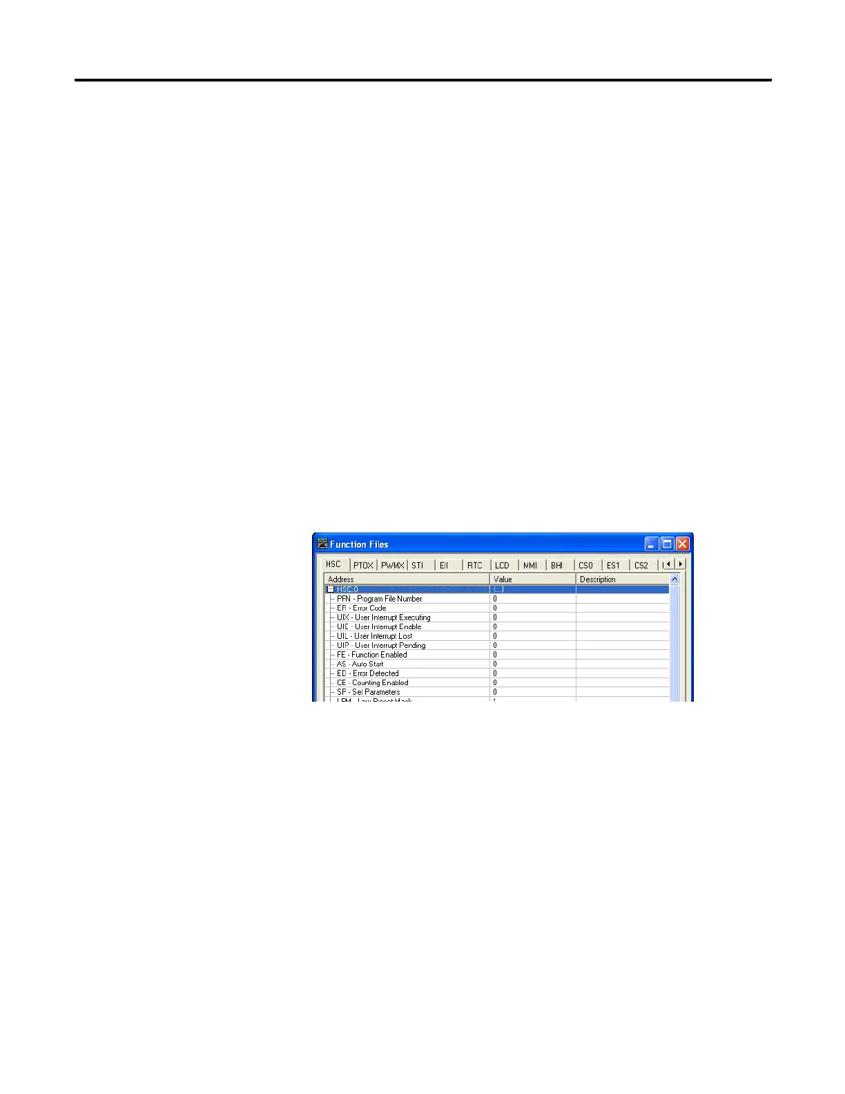
Locate the Function Files under Controller in RSLogix 500/RSLogix Micro
and select the HSC tab, then select the [+] next to HSC:0 (See Below)
Enter the following parameters for the “Minimum Configuration”
required for the HSC to count pulses.
Note: There is no additional ladder logic required to enable the High
Speed Counter. In other words there is no HSC instruction needed for the
ladder logic program.
HSC:0.PFN Program File Number defines which subroutine is executed when the HSC:0 accumulated
count equals the High or Low preset or passes through Overflow or Underflow. The
Integer number entered must be a valid sub-routine program file (3…255).
efesotomasyon.com - Allen Bradley,Rockwell,plc,servo,drive

 Loading...


