Publication 1766-RM001A-EN-P - October 2008
Process Control Instruction 349
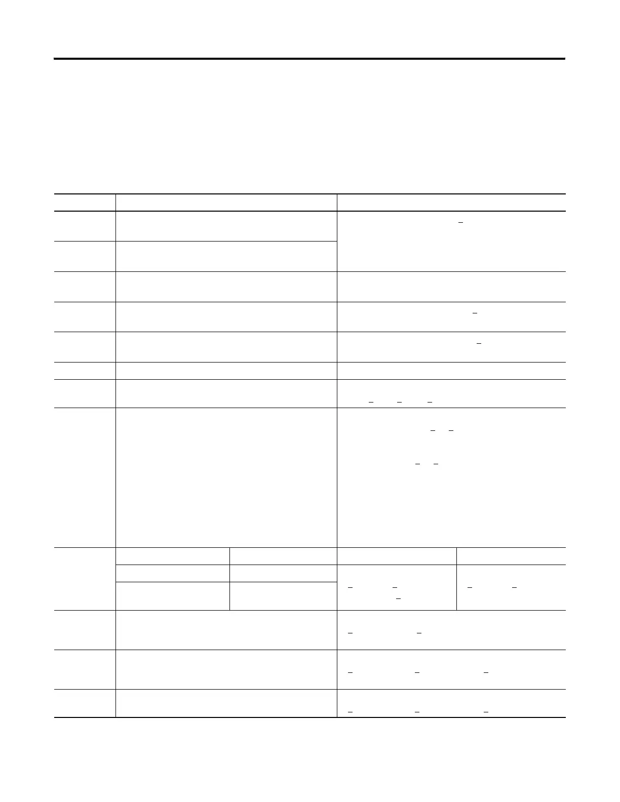
Runtime Errors
Error code 0036 appears in the status file when a PID instruction runtime
error occurs. Code 0036 covers the following PID error conditions, each
of which has been assigned a unique single byte code value that appears
in the MSB of the second word of the control block. The error code is also
displayed on the PID Setup Screen in RSLogix 500/RSLogix Micro.
Error Code Description of Error Condition or Conditions Corrective Action
11H 1. Loop update time
D
t
> 1024
Change loop update time 0 < D
t
< 1024
2. Loop update time
D
t
= 0
12H Proportional gain
K
c
< 0
Change proportional gain K
c
to 0 < K
c
13H Integral gain (reset)
T
i
< 0
Change integral gain (reset) T
i
to 0 < T
i
14H Derivative gain (rate)
T
d
< 0
Change derivative gain (rate) T
d
to 0 < T
d
15H Feed Forward Bias (FF) is out-of-range. Change FF so it is within the range -16383…+16383.
23H Scaled setpoint min
MinS > Scaled setpoint max MaxS
Change scaled setpoint min MinS to
-32768 <
MinS < MaxS < +32767
31H If you are using setpoint scaling and
MinS > setpoint SP > MaxS, or
If you are not using setpoint scaling and
0 > setpoint SP > 16383,
then during the initial execution of the PID loop, this error
occurs and bit 11 of word 0 of the control block is set.
However, during subsequent execution of the PID loop if
an invalid loop setpoint is entered, the PID loop continues
to execute using the old setpoint, and bit 11 of word 0 of
the control block is set.
If you are using setpoint scaling, then change
the setpoint SP to MinS <
SP < MaxS, or
If you are not using setpoint scaling, then change
the setpoint SP to 0 <
SP < 16383.
41H Scaling Selected Scaling Deselected Scaling Selected Scaling Deselected
1. Deadband < 0, or 1. Deadband < 0, or Change deadband to
0 <
deadband <
(MaxS - MinS) <
16383
Change deadband to
0 <
deadband < 16383
2. Deadband
>
(MaxS – MinS)
2. Deadband > 16383
51H 1. Output high limit < 0, or
2. Output high limit > 100
Change output high limit to
0 <
output high limit < 100
52H 1. Output low limit < 0, or
2. Output low limit > 100
Change output low limit to
0 <
output low limit < output high limit < 100
53H Output low limit > output high limit Change output low limit to
0 <
output low limit < output high limit < 100
efesotomasyon.com - Allen Bradley,Rockwell,plc,servo,drive

 Loading...


