Publication 1766-RM001A-EN-P - October 2008
LCD - LCD Information 535
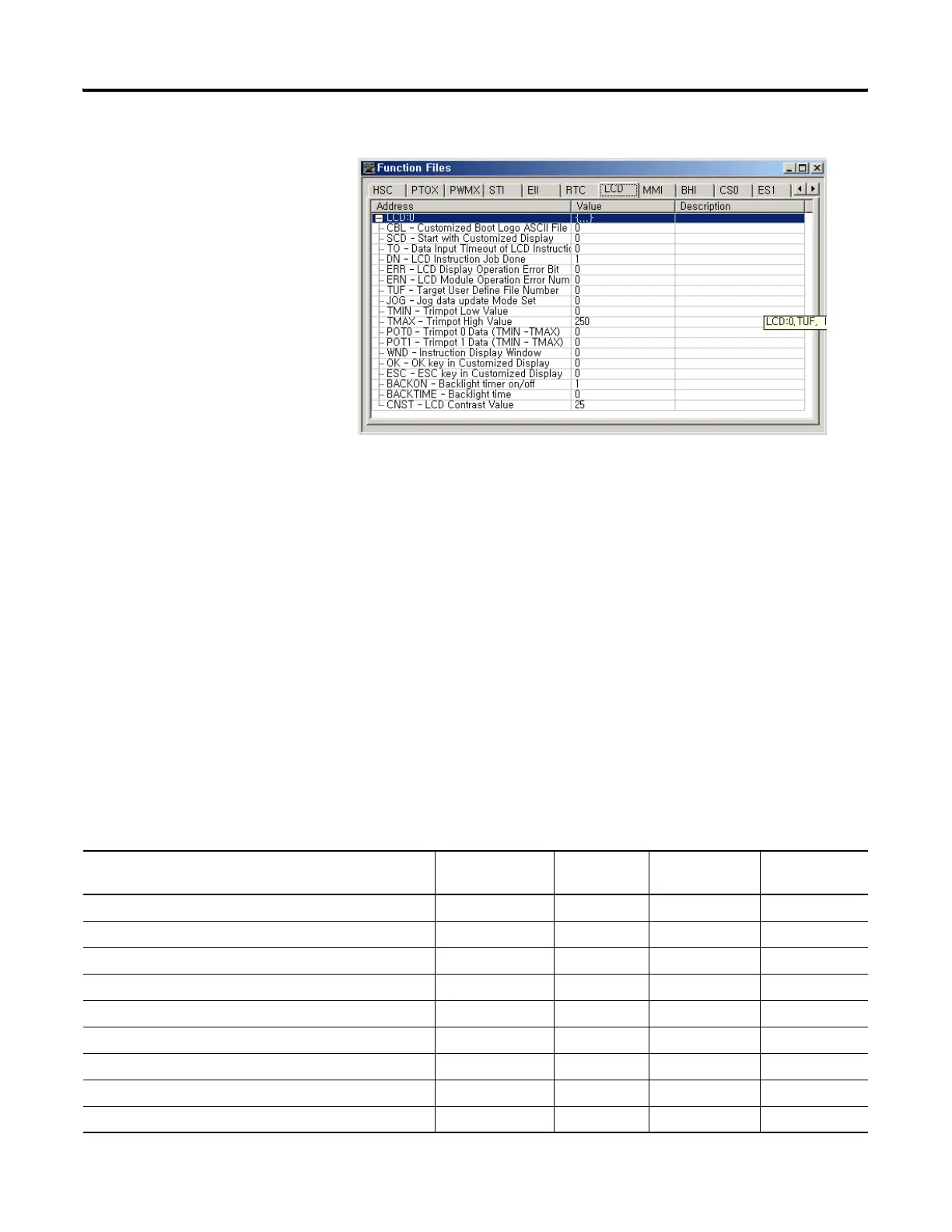
The LCD Function File contains status information and control
configurations for LCD, Trimpot, and keypad, such as:
• Information about whether to use a customized display at power-up
• Keypad key-in mode and timeout settings
• Bit, Integer and Long Integer data files to monitor
• Current Trimpot values and Trimpot value range settings
LCD Function File
Sub-Elements Summary
LCD function file is comprised of 15 sub-elements. These sub-elements
are either bit, word structures that are used to provide control over LCD,
Keypad, Trimpot. A summary of the sub-element is provided in the
following table.
LCD Function File
Feature Address Data Format Type User Program
Access
CBL - Customized Boot Logo ASCII file Address LCD:0.CBL word (INT) control read/write
SCD - Start with Customized Display LCD:0/SCD binary (bit) control read-only
TO - Data Input Timeout of LCD instruction LCD:0.TO word (INT) control read-only
DN - LCD Instruction Job Done LCD:0/DN binary (bit) status read-only
ERR - LCD Display Operation Error Bit LCD:0/ERR binary (bit) status read-only
ERN - LCD Module Operation Error Number LCD:0.ERN word (INT) status read-only
TUF- Target User Defined File Number LCD:0.TUF word (INT) control read-only
JOG - Jog data update Mode set LCD:0/JOG binary (bit) control read/write
TMIN - Trimpot low value LCD:0.TMIN word (INT) control read-only
efesotomasyon.com - Allen Bradley,Rockwell,plc,servo,drive

 Loading...


