Publication 1766-RM001A-EN-P - October 2008
Conversion Instructions 253
GCD - Gray Code
Instruction Type: output
The GCD instruction converts Gray code data (Source) to an integer value
(Destination). If the Gray code input is negative (high bit set), the
Destination is set to 32767 and the overflow flag is set.
Addressing Modes and File Types are shown in the following table:
Updates to Math Status Bits
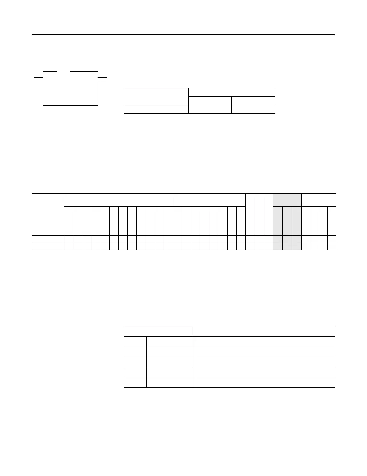
GCD
Gray Code
Source I1:2.0
225<
Dest N7:1
190<
GCD
Execution Time for the GCD Instructions
Controller When Rung Is:
True False
MicroLogix 1400 5.4970 µs 0.5618 µs
GCD Instruction Valid Addressing Modes and File Types
For definitions of the terms used in this table see Using the Instruction Descriptions on page 4-2.
Parameter
Data Files Function Files
CS - Comms
IOS - I/O
DLS - Data Log
Address
Mode
Address Level
O
I
S
B
T, C, R
N
F
ST
L
MG, PD
RI/RIX
PLS
RTC
HSC
PTOX, PWMX
STI
EII
BHI
MMI
LCD
Immediate
Direct
Indirect
Bit
Word
Long Word
Element
Source •• ••• • • ••
Destination • • • • • •
• ••
Math Status Bits
With this Bit: The Controller:
S:0/0 Carry always reset
S:0/1 Overflow set if the Gray code input is negative, otherwise is reset
S:0/2 Zero Bit set if the destination is zero, otherwise reset
S:0/3 Sign Bit always reset
S:5/0 Overflow Trap set if the Overflow Bit is set, otherwise reset
efesotomasyon.com - Allen Bradley,Rockwell,plc,servo,drive

 Loading...


