Publication 1766-RM001A-EN-P - October 2008
Sequencer Instructions 291
SQO- Sequencer Output
Instruction Type: output
On a false-to-true rung transition, the SQO instruction transfers masked
source reference words or long words to the destination for the control of
sequential machine operations. When the rung goes from false-to-true, the
instruction increments to the next step (word) in the sequencer file. Data
stored there is transferred through a mask to the destination address
specified in the instruction. Data is written to the destination word every
time the instruction is executed.
The done bit is set when the last word of the sequencer file is transferred.
On the next false-to-true rung transition, the instruction resets the position
to step one.
If the position is equal to zero at start-up, when you switch the controller
from the program mode to the run mode, the instruction operation
depends on whether the rung is true or false on the first scan.
• If the rung is true, the instruction transfers the value in step zero.
• If the rung is false, the instruction waits for the first rung transition
from false-to-true and transfers the value in step one.
Position • •
(1) See Important note about indirect addressing.
(2) Control file only.
SQC Instruction Valid Addressing Modes and File Types
For definitions of the terms used in this table see Using the Instruction Descriptions on page 92.
Parameter
Data Files Function Files
CS - Comms
IOS - I/O
DLS - Data Log
Address
Mode
(1)
Address Level
O
I
S
B
T, C, R
N
F
ST
L
MG, PD
RI/RIX
PLS
RTC
HSC
PTOX, PWMX
STI
EII
BHI
MMI
LCD
Immediate
Direct
Indirect
Bit
Word
Long Word
Element
IMPORTANT
You cannot use indirect addressing with: S, MG, PD, RTC, HSC, PTOX,
PWMX, STI, EII, BHI, MMI, CS, IOS, LCD, and DLS files.
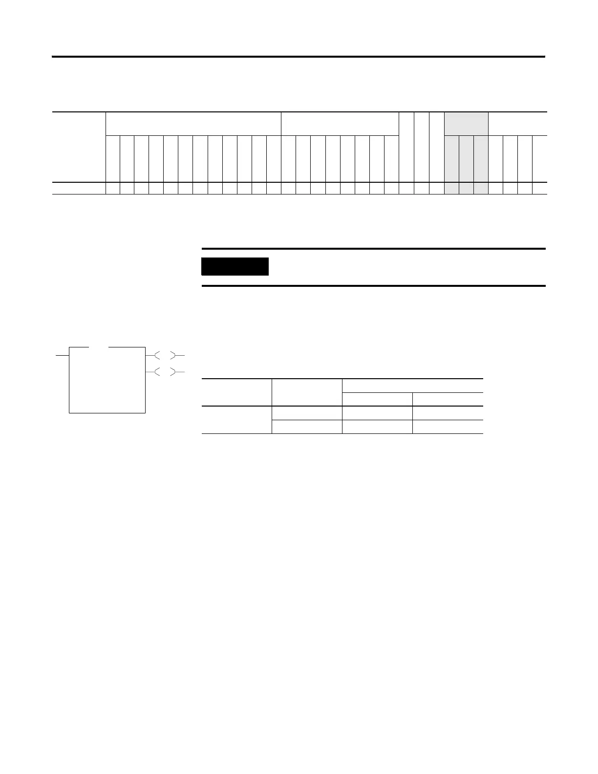
EN
DN
SQO
Sequencer Output
File #B3:0
Mask N7:0
Dest N7:1
Control R6:0
Length 1<
Position 0<
SQO
Execution Time for the SQO Instruction
Controller Data Size When Rung Is:
True False
MicroLogix 1400 word 3.6105 µs 0.9480 µs
Long word 3.1920 µs 1.1850 µs
efesotomasyon.com - Allen Bradley,Rockwell,plc,servo,drive

 Loading...


