Publication 1766-RM001A-EN-P - October 2008
374 ASCII Instructions
Example
In this example, when the rung goes from false-to-true, the control
element Enable (EN) bit is set. When the instruction is placed in the ASCII
queue, the Queue bit (EU) is set. The Running bit (RN) is set when the
instruction is executing. The DN bit is set on completion of the
instruction.
Forty characters from string ST37:40 are sent through channel 0. The
Done bit (DN) is set and a value of 40 is present in the POS word of the
ASCII control data file.
When an error is detected, the error code is written to the Error Code Byte
and the Error Bit (ER) is set. See ASCII Instruction Error Codes on page
390 for a list of the error codes and recommended action to take.
ABL - Test Buffer for Line
Instruction Type: output
The ABL instruction is used to determine the number of characters in the
receive buffer of the specified communication channel, up to and
including the end-of-line characters (termination). This instruction looks
for the two termination characters that you configure via the channel
configuration screen. On a false-to-true transition, the controller reports
the number of characters in the POS field of the control data file. The
channel configuration must be set to ASCII.
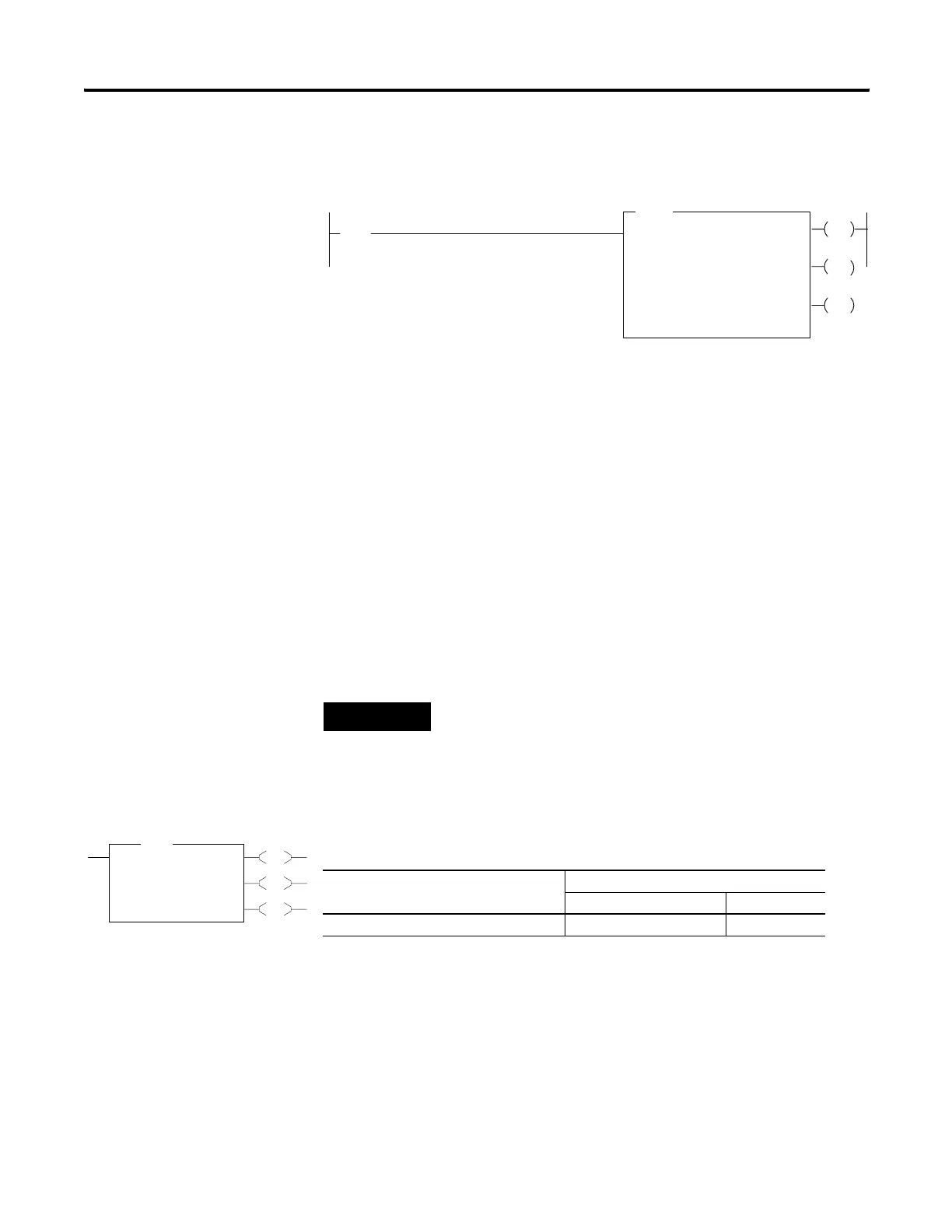
AWT
ASCII WRITE
Channel
Source
I:1
10
[
[
Control
0
ST37:20
R6:23
String Length
Characters Sent
40
0
0
EN
DN
ER
Error
If input slot 1, bit 10 is set, write 40 characters from
ST37:20 to the display device.
TIP
For information on the timing of this instruction, see the timing diagram on
page 389.
EN
DN
ER
ABL
Ascii Test For Line
Channel 0
Control R6:0
Characters 1<
Error 0<
ABL
Execution Time for the ABL Instruction
Controller When Instruction Is:
True False
MicroLogix 1400 21.5621 µs 1.8710 µs
efesotomasyon.com - Allen Bradley,Rockwell,plc,servo,drive

 Loading...


