297 Publication 1766-RM001A-EN-P - October 2008
Chapter
17
Program Control Instructions
Use these instructions to change the order in which the processor scans a
ladder program. Typically these instructions are used to minimize scan
time, create a more efficient program, and troubleshoot a ladder program.
JMP - Jump to Label
Instruction Type: output
The JMP instruction causes the controller to change the order of ladder
execution. Jumps cause program execution to go to the rung marked LBL
label number. Jumps can be forward or backward in ladder logic within
the same program file. Multiple JMP instructions may cause execution to
proceed to the same label.
The immediate data range for the label is from 0…999. The label is local
to a program file.
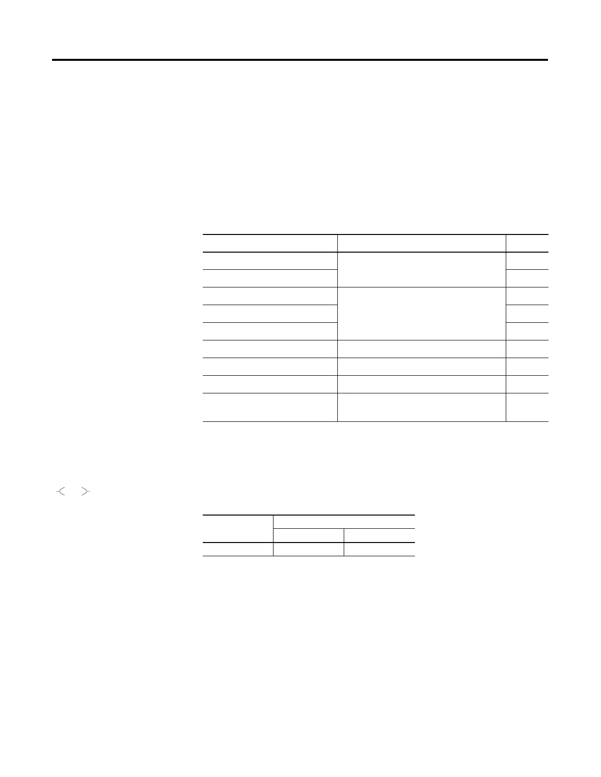
Instruction Used To: Page
JMP - Jump to Label Jump forward/backward to a corresponding
label instruction
297
LBL - Label 298
JSR - Jump to Subroutine Jump to a designated subroutine and return 298
SBR - Subroutine Label 298
RET - Return from Subroutine 299
SUS - Suspend Debug or diagnose your user program 299
TND - Temporary End Abort current ladder scan 299
END - Program End End a program or subroutine 300
MCR - Master Control Reset Enable or inhibit a master control zone in
your ladder program
300
JMP
Q2:0
Execution Time for the JMP Instruction
Controller When Rung Is:
True False
MicroLogix 1400 0.3290 µs 0.2320 µs
efesotomasyon.com - Allen Bradley,Rockwell,plc,servo,drive

 Loading...


