533 Publication 1766-RM001A-EN-P - October 2008
Chapter
25
LCD - LCD Information
This chapter describes how to use the LCD functions.
LCD Overview
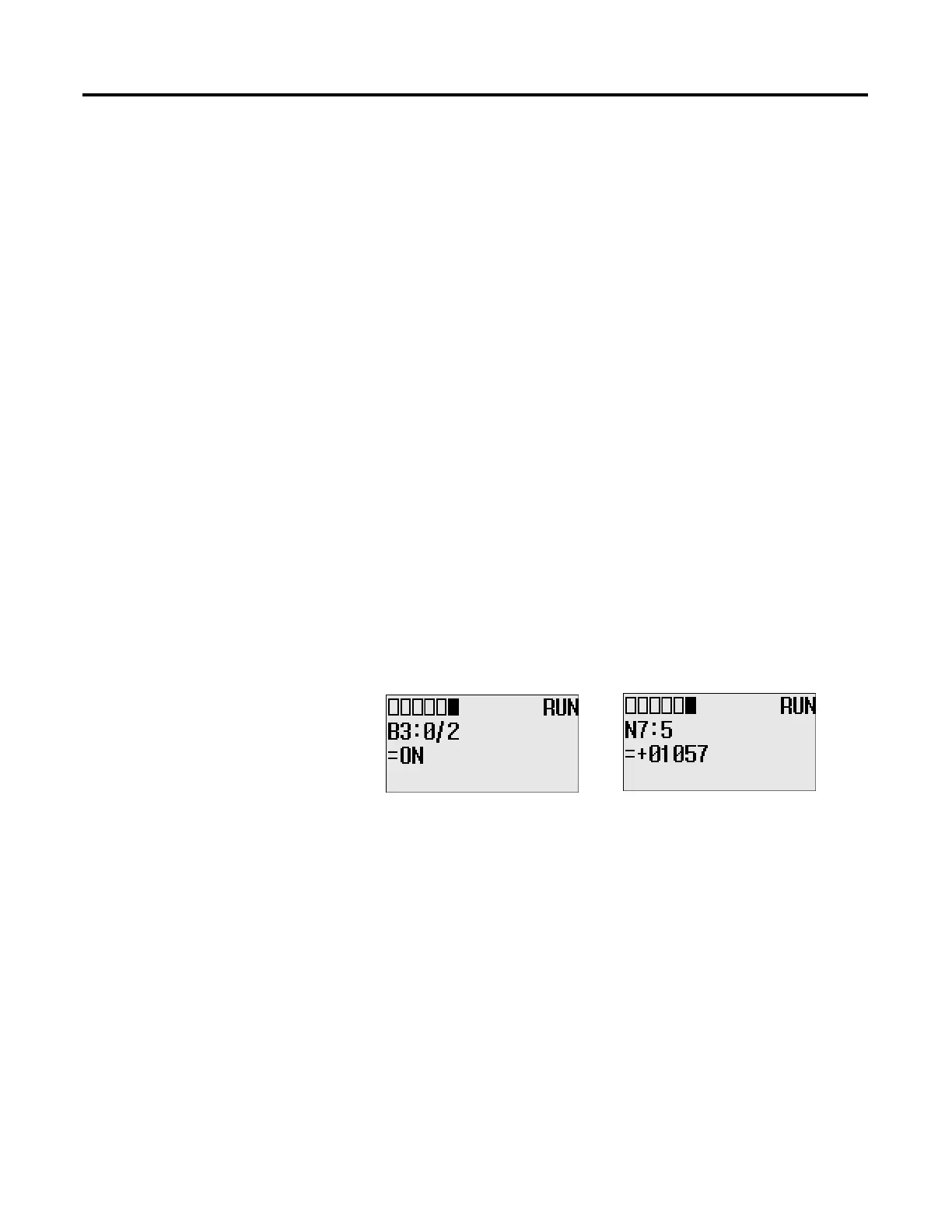
Through the embedded LCD, your MicroLogix 1400 lets you monitor bit,
integer and long integer data within the controller, and optionally modify
that data, to interact with your control program. Similarly to the optional
1764-DAT for the MicroLogix 1500 controllers, the embedded MicroLogix
1400 LCD allows users access to 256 bits, 256 integers and 256 long
integers, each of which can be individually protected. If you need to
know the speed of a conveyor, the status of a remote sensor, or how close
your process is running relative to its optimal temperature, you can just
monitor your LCD.
You can manually start an operation, change a timing sequence, or make
adjustments to a counter, and use the LCD to simulate pushbuttons or
numeric entry devices. By simply moving or copying data in and out of
the bit and integer files, you now can monitor and modify the parameters
that your controller uses.
Making use of the new MicroLogix 1400 “LCD Instruction”, your controller
can directly interface with a local operator using your ladder logic. The
LCD Instruction executes under two modes of operation, the first mode
being ladder logic output to the display only (hereafter called “Display
Only mode”). In this Display Only mode, up to three lines of data, with
up to 16 characters per line, can be sent to the display from the ladder
logic running in the controller. Think of this as messaging to the LCD.
These lines can consist of combinations of Bits, Integers, Long Integers,
Floating and String characters. So now the control program can send alert/
alarm messages, I/O data values, simple text messages, or combinations
of these messages to the operator. These messages can be triggered by
events (input sensors, timer “done bits”, message from another controller,
etc.), or based on a scheduled action (using the embedded real time
clock, or free running timers).
efesotomasyon.com - Allen Bradley,Rockwell,plc,servo,drive

 Loading...


