Publication 1766-RM001A-EN-P - October 2008
282 File Instructions
LFL - Last In, First Out
(LIFO) Load
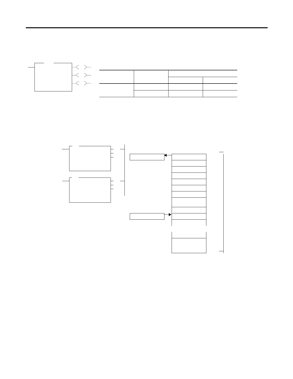
Instruction Type: output
On a false-to-true rung transition, the LFL instruction loads words or long
words into a user-created file called a LIFO stack. This instruction’s
counterpart, LIFO unload (LFU), is paired with a given LFL instruction to
remove elements from the LIFO stack. Instruction parameters have been
programmed in the LFL - LFU instruction pair shown below.
This instruction uses the following operands:
• Source - The source operand is a constant or address of the value
used to fill the currently available position in the LIFO stack. The
data size of the source must match the LIFO stack. If LIFO is a word
size file, source must be a word value or constant. If LIFO is a long
word size file, source must be a long word value or constant. The
data range for the source is from -32768…32767 (word) or
-2,147,483,648…2,147,483,647 (long word).
• LIFO - The LIFO operand is the starting address of the stack.
EN
DN
EM
LFL
LIFO Load
Source N7:0
LIFO #N7:1
Control R6:0
Length 1<
Position 0<
LFL
Execution Time for the LFL Instruction
Controller Data Size When Rung Is:
True False
MicroLogix 1400 word 6.4950 µs 6.5650 µs
long word 7.3570 µs 7.0030 µs
(DN)
(EN)
(DN)
(EM)
LFL
LIFO LOAD
Source N7:10
LIFO #N7:12
Control R6:0
Length 34
Position 9
(EU)
(EM)
LIFO UNLOAD
LIFO #N7:12
Dest N7:11
Control R6:0
Length 34
Position 9
LFU
Destination Position
N7:11 N7:12 0
N7:13 1
LFU instruction
unloads data from
stack #N7:12 at
position 0, N7:12
N7:14 2
3
4
5 34 words are allocated
for FIFO stack starting
at N7:12, ending at
N7:45
6
7
Source 8
N7:10 9
LFL instruction loads
data into stack
#N7:12 at the next
available position, 9
in this case.
N7:45 33
Loading and Unloading of Stack #N7:12
LFL and LFU Instruction Pair
efesotomasyon.com - Allen Bradley,Rockwell,plc,servo,drive

 Loading...


