Publication 1766-RM001A-EN-P - October 2008
274 File Instructions
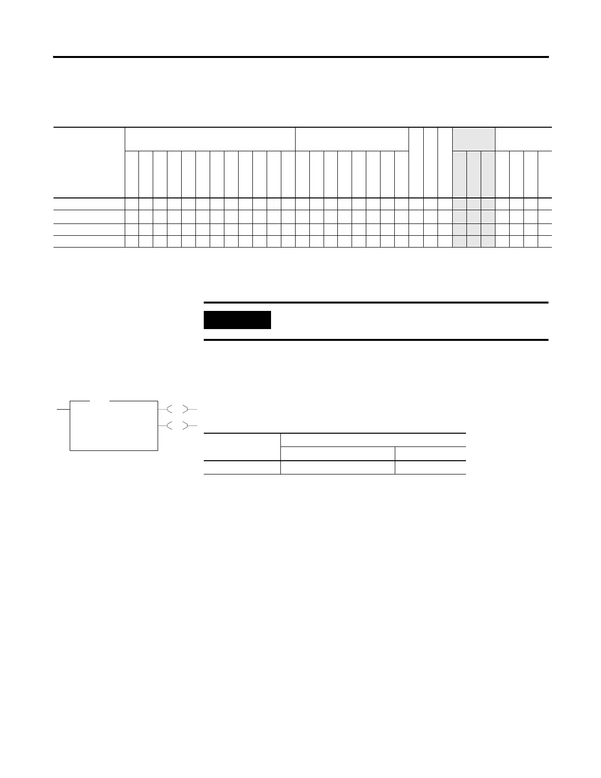
BSR - Bit Shift Right
Instruction Type: output
If you wish to shift more than one bit per scan, you must create a loop in
your application using the JMP, LBL, and CTU instructions.
The BSR instruction loads data into a bit array on a false-to-true rung
transition, one bit at a time. The data is shifted right through the array,
then unloaded, one bit at a time. The following figure shows the
operation of the BSR instruction.
BSL Instruction Valid Addressing Modes and File Types
For definitions of the terms used in this table see Using the Instruction Descriptions on page 92.
Parameter
Data Files Function Files
CS - Comms
IOS - I/O
DLS - Data Log
Address
Mode
(1)
Address Level
O
I
S
B
T, C, R
N
F
ST
L
MG, PD
RI/RIX
PLS
RTC
HSC
PTOX, PWMX
STI
EII
BHI
MMI
LCD
Immediate
Direct
Indirect
Bit
Word
Long Word
Element
File •••• •• • •••
Control
(2)
• •
Length
• •
Source •• ••• •
• ••
(1) See Important note about indirect addressing.
(2) Control file only. Not valid for Timers and Counters.
IMPORTANT
You cannot use indirect addressing with: S, MG, PD, RTC, HSC, PTOX,
PWMX, STI, EII, BHI, MMI, CS, IOS, and DLS files.
EN
DN
BSR
Bit Shift Right
File #B3:3
Control R6:0
Bit Address I:0/15
Length 1<
BSR
Execution Time for the BSR Instruction
Controller When Rung Is:
True False
MicroLogix 1400 6.0790 µs 5.9942 µs
efesotomasyon.com - Allen Bradley,Rockwell,plc,servo,drive

 Loading...


