Publication 1766-RM001A-EN-P - October 2008
File Instructions 275
This instruction uses the following operands:
• File - The file operand is the address of the bit array that is to be
manipulated.
• Control - The control operand is the address of the BSR’s control
element. The control element consists of 3 words:
• Bit Address - The source is the address of the bit to be transferred
into the bit array at the last (highest) bit position.
• Length - The length operand contains the length of the bit array in
bits. The data range for length is from 0…2048.
Addressing Modes and File Types can be used as shown in the following
table:
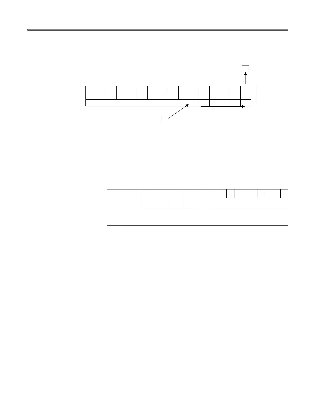
Data block is shifted one bit at
a time from bit 69…32.
Source Bit
I:23/06
38 Bit Array
#B3:2
Unload Bit
(R6:0/10)
47 46 45 44 43 42 41 40 39 38 37 36 35 34 33 32
63 62 61 60 59 58 57 56 55 54 53 52 51 50 49 48
INVALID 696867666564
15 14 13 12 11 10 9876543210
Word 0
EN
(1)
(1) EN - Enable Bit is set on false-to-true transition of the rung and indicates the instruction is enabled.
--
DN
(2)
(2) DN - Done Bit, when set, indicates that the bit array has shifted one position.
--
ER
(3)
(3) ER - Error Bit, when set, indicates that the instruction detected an error such as entering a negative number for the
length or source operand.
UL
(4)
(4) UL - Unload Bit is the instruction’s output. Avoid using the UL (unload) bit when the ER (error) bit is set.
not used
Word 1 Size of bit array (number of bits).
Word 2 not used
efesotomasyon.com - Allen Bradley,Rockwell,plc,servo,drive

 Loading...


