Publication 1766-RM001A-EN-P - October 2008
18 I/O Configuration
MicroLogix 1400
Expansion I/O Memory
Mapping
Discrete I/O Configuration
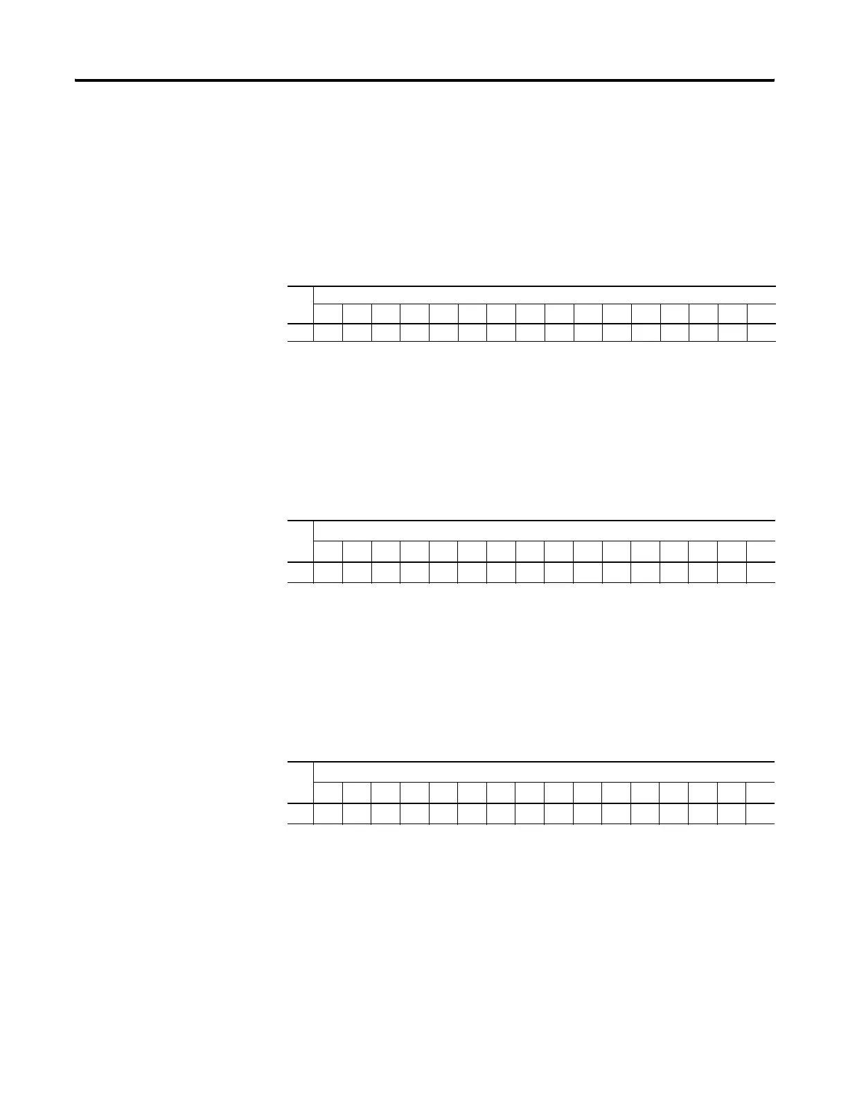
1762-IA8 ,1762-IQ8, and 1762-IQ8OW6 Input Image
For each input module, the input data file contains the current state of the
field input points. Bit positions 0…7 correspond to input terminals 0…7.
r = read only, x = not used, always at a 0 or OFF state
1762-IQ16 Input Image
For each input module, the input data file contains the current state of the
field input points. Bit positions 0…15 correspond to input terminals
0…15.
r = read only
1762-OX6I and 1762-IQ8OW6 Output Image
For each output module, the output data file contains the
controller-directed state of the discrete output points. Bit positions 0…5
correspond to output terminals 0…5.
r/w = read and write, 0 = always at a 0 or OFF state
1762-OA8, 1762-OB8, and 1762-OW8 Output Image
For each output module, the output data file contains the
controller-directed state of the discrete output points. Bit positions 0…7
correspond to output terminals 0…7.
Word
Bit Position
15 14 13 12 11 10 9 8 7 6 5 4 3 2 1 0
0xxxxxxxxrrrrrrrr
Word
Bit Position
1514131211109876543210
0rrrrrrrrrrrrrrrr
Word
Bit Position
15 14 13 12 11 10 9 8 7 6 5 4 3 2 1 0
00000000000r/wr/wr/wr/wr/wr/w
efesotomasyon.com - Allen Bradley,Rockwell,plc,servo,drive

 Loading...


