EasyManuals Logo

Allen-Bradley MicroLogix 1400 User Manual

Allen-Bradley MicroLogix 1400
694 pages
To Next Page IconTo Next Page
To Previous Page IconTo Previous Page
Page #353 background imageLoading...
Page #353 background image
Publication 1766-RM001A-EN-P - October 2008
Process Control Instruction 351
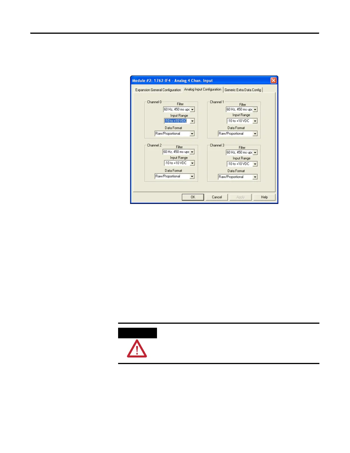
The configuration for the analog output is virtually identical. Simply
address the PID control variable (CV) to the analog output address and
configure the analog output to “Scaled for PID” behavior.
Application Notes
The following paragraphs discuss:
Input/Output Ranges
Scaling to Engineering Units
Zero-crossing Deadband
Output Alarms
Output Limiting with Anti-reset Windup
The Manual Mode
Feed Forward
ATTENTION
Do not alter the state of any PID control block value unless you fully
understand its function and how it will affect your process. Unexpected
operation could result with possible equipment damage and/or personal
injury.
efesotomasyon.com - Allen Bradley,Rockwell,plc,servo,drive

Table of Contents

Other manuals for Allen-Bradley MicroLogix 1400

Questions and Answers:

Question and Answer IconNeed help?

Do you have a question about the Allen-Bradley MicroLogix 1400 and is the answer not in the manual?

Allen-Bradley MicroLogix 1400 Specifications

General IconGeneral
Processor32-bit
Expansion ModulesUp to 7 expansion I/O modules
Power Supply24V DC or 120/240V AC
Programming SoftwareRSLogix 500
Communication PortsEthernet, RS-232/RS-485 combo port
Controller TypeProgrammable Logic Controller (PLC)
SeriesMicroLogix
Digital Outputs12
Analog Inputs6 (embedded)
Analog Outputs2 (embedded)
High-Speed Counter6 high-speed counters
Pulse Output2 (embedded)
Ethernet PortYes

Related product manuals