Publication 1766-RM001A-EN-P - October 2008
34 I/O Configuration
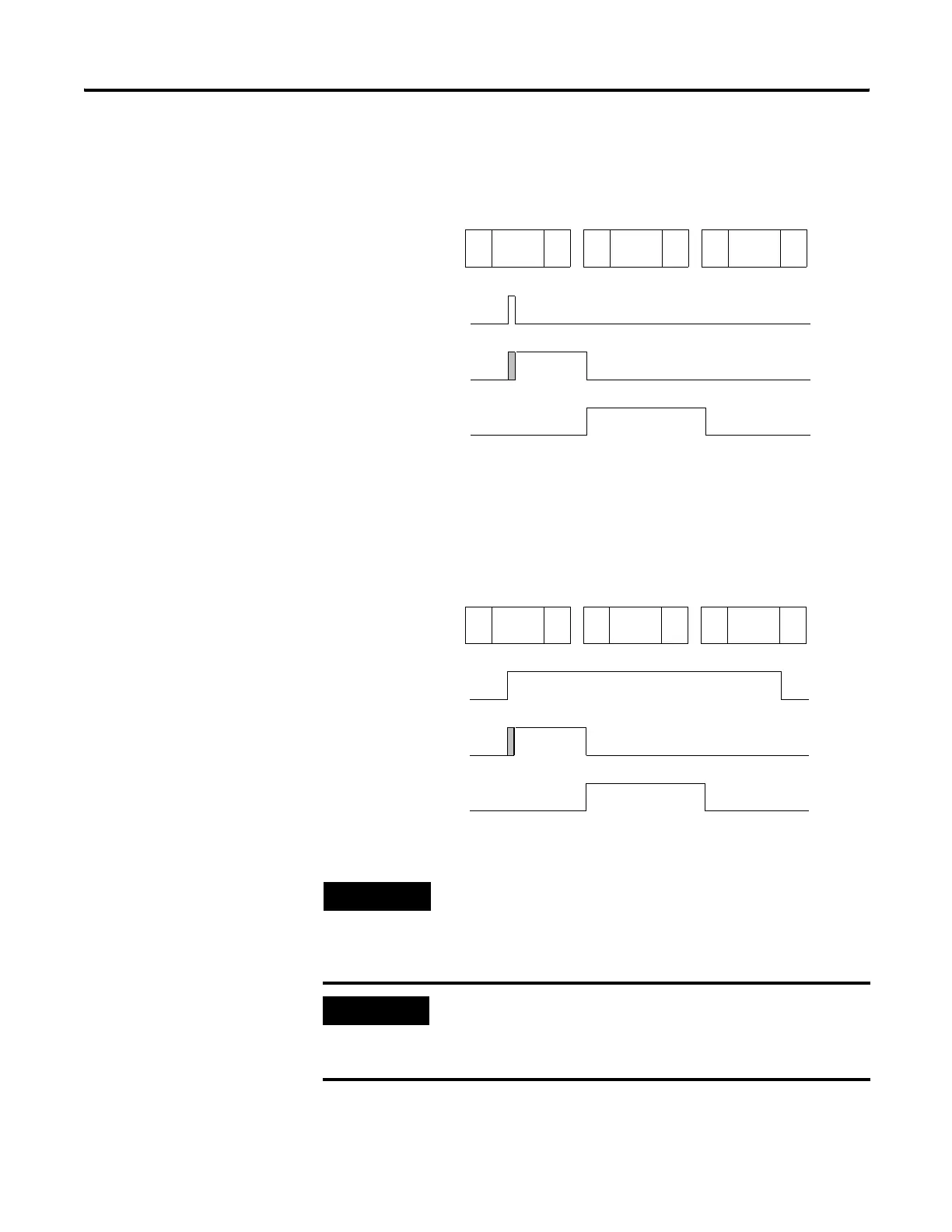
Rising Edge Behavior - Example 1
Rising Edge Behavior - Example 2
The previous examples demonstrate rising edge behavior. Falling edge
behavior operates exactly the same way with these exceptions:
TIP
The “gray” area of the Latched Status waveform is the input filter delay.
IMPORTANT
The input file value does not represent the external input when the input is
configured for latching behavior. When configured for rising edge behavior,
the input file value is normally “off” (“on” for 1 scan when a rising edge
pulse is detected).
Scan Number (X) Scan Number (X+1) Scan Number (X+2)
External
Input
Latched
Status
Input File
Value
Input
Scan
Ladder
Scan
Output
Scan
Input
Scan
Ladder
Scan
Output
Scan
Input
Scan
Ladder
Scan
Output
Scan
Scan Number (X) Scan Number (X+1) Scan Number (X+2)
External
Input
Latched
Status
Input File
Value
Input
Scan
Ladder
Scan
Output
Scan
Input
Scan
Ladder
Scan
Output
Scan
Input
Scan
Ladder
Scan
Output
Scan
efesotomasyon.com - Allen Bradley,Rockwell,plc,servo,drive

 Loading...


