Publication 1766-RM001A-EN-P - October 2008
170 Relay-Type (Bit) Instructions
Addressing Modes and File Types can be used as shown in the following
table:
OTL - Output Latch
OTU - Output Unlatch
Instruction Type: output
The OTL and OTU instructions are retentive output instructions. OTL
turns on a bit, while OTU turns off a bit. These instructions are usually
used in pairs, with both instructions addressing the same bit.
Since these are latching outputs, once set (or reset), they remain set (or
reset) regardless of the rung condition.
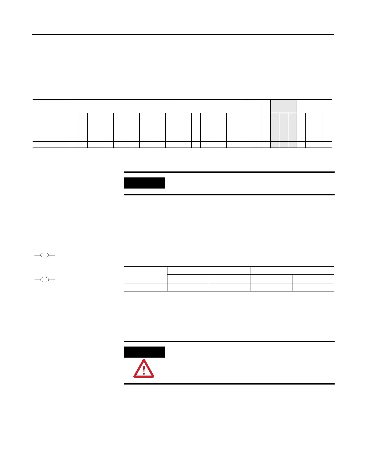
OTE Instruction Valid Addressing Modes and File Types
For definitions of the terms used in this table see Using the Instruction Descriptions on page 92.
Parameter
Data Files
Function Files
(1)
CS - Comms
IOS - I/O
DLS - Data Log
Address
Mode
(2)
Address Level
O
I
S
B
T, C, R
N
F
ST
L
MG, PD
RI/RIX
PLS
RTC
HSC
PTOX, PWMX
STI
EII
BHI
MMI
LCD
Immediate
Direct
Indirect
Bit
Word
Long Word
Element
Destination Bit •••••• •• ••••• • • ••
(1) PTOX and PWMX files are only for use with MicroLogix 1400 BXB or BXBA unit.
(2) See Important note about indirect addressing.
IMPORTANT
You cannot use indirect addressing with: S, MG, PD, RTC, HSC, PTOX,
PWMX, STI, EII, BHI, MMI, LCD, CS, IOS, and DLS files.
L
B3:0
1
U
B3:0
1
Execution Time for the OTL and OTU Instructions
Controller OTL - When Rung Is: OTU - When Rung Is:
True False True False
MicroLogix 1400 0.2541 µs 0.1882 µs 0.2830 µs 0.1732 µs
ATTENTION
If you enable interrupts during the program scan via an OTL, OTE, or UIE,
this instruction must be the last instruction executed on the rung (last
instruction on last branch). It is recommended this be the only output
instruction on the rung.
efesotomasyon.com - Allen Bradley,Rockwell,plc,servo,drive

 Loading...


