Publication 1766-RM001A-EN-P - October 2008
Knowledgebase Quick Starts 635
Example
The following example uses the HSC in Mode 0 - “Up Counter”. The “Up
Counter” clears the accumulated value (0) when it reaches the High
Preset (HIP). This mode configures I1:0.0/0 (I:0/0) as the HSC:0 input.
Note:
Each mode for the HSC will configure the inputs for different
functionality.
In this example the HSC will count input pulses coming into I:0/0, when
the total number of pulses counted equals the High Preset (HIP) the HSC
will jump to subroutine file #3
The HIP is set for 5000 pulses in this example, Also once the HIP is
reached the HSC will then reset HSC:0.ACC to zero (0) and start counting
again.
Important:
It is assumed that the user has connected a device to I:0/0
to generate pulses.
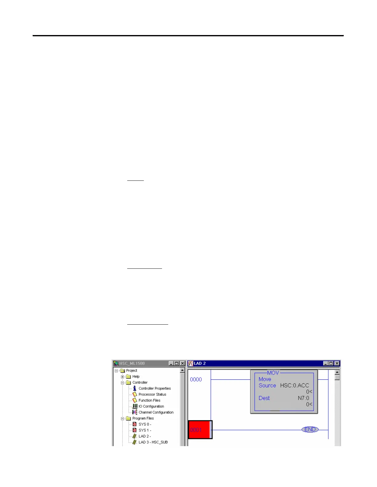
Note: The following ladder logic does not need to be entered into File #2,
however this allows for easy viewing of the accumulated counts from the
HSC:0.ACC.
IMPORTANT:
Ladder Logic Subroutine file #3 must be created in order for
this example to work. If the subroutine is not created the CPU will fault
due to an HSC Error Code 1 - Invalid File Number for PFN has been
entered.
HSC:0/AS Auto-Start defines if the HSC function will automatically start when the MicroLogix enters
run or test.
HSC:0/CE Counting Enabled control bit is used to enable or disable the HSC
HSC:0.HIP High Preset is the upper set point (in counts) that defines when the HSC will generate an
interrupt and execute the PFN sub-routine.
efesotomasyon.com - Allen Bradley,Rockwell,plc,servo,drive

 Loading...


