Publication 1766-RM001A-EN-P - October 2008
280 File Instructions
• Destination - The destination operand is a word or long word
address that stores the value which exits from the FIFO stack. The
FFU instruction unloads this value from the first location on the
FIFO stack and places it in the destination address. The address
level of the destination must match the FIFO stack. If FIFO is a word
size file, destination must be a word size file. If FIFO is a long word
size file, destination must be a long word size file.
• Control - This is a control file address. The status bits, stack length,
and the position value are stored in this element. The control
element consists of 3 words:
• Length - The length operand contains the number of elements in the
FIFO stack. The length of the stack can range from 1…128 (word) or
1…64 (long word).
• Position - Position is a component of the control register. The
position can range from 0…127 (word) or 0…63 (long word). The
position is decremented after each unload. Data is unloaded at
position zero.
Addressing Modes and File Types can be used as shown in the following
table:
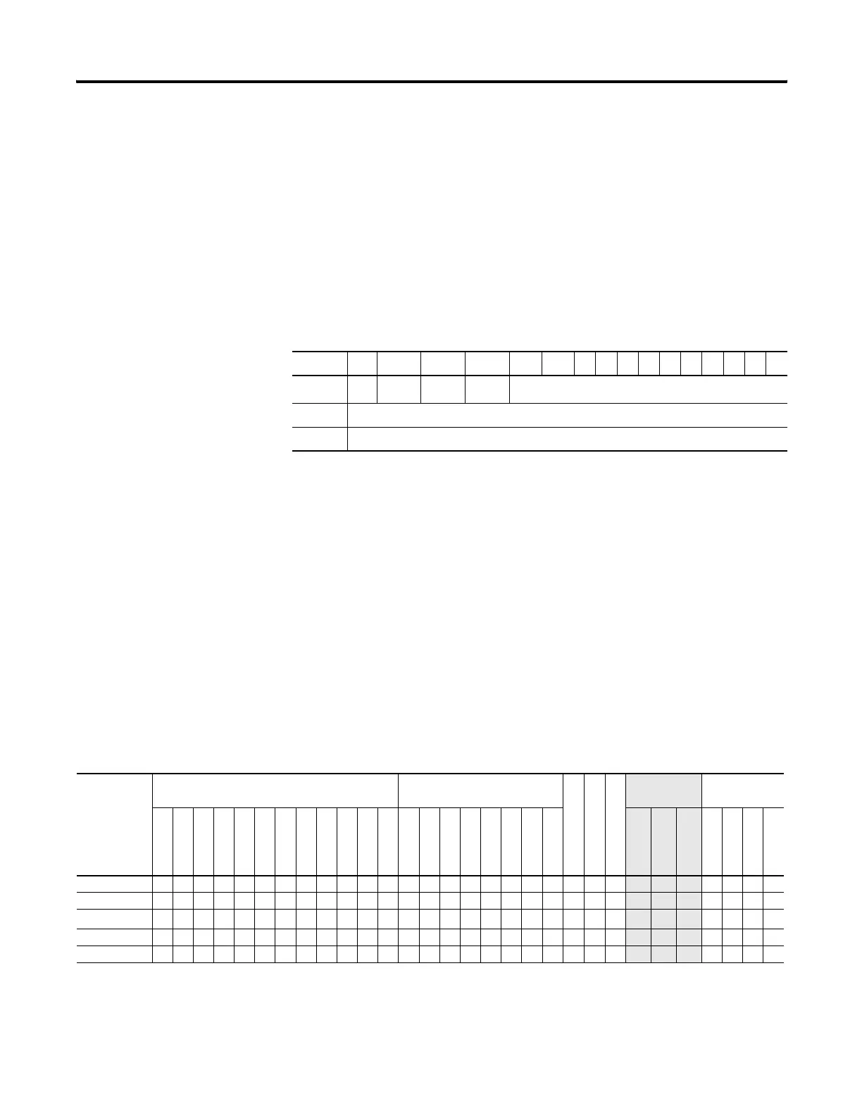
1514 13 12 11 10 9876543210
Word 0 --
EU
(1)
(1) EU - Enable Unload Bit is set on false-to-true transition of the rung and indicates the instruction is enabled.
DN
(2)
(2) DN - Done Bit, when set, indicates that the stack is full.
EM
(3)
(3) EM - Empty Bit, when set, indicates FIFO is empty.
not used
Word 1 Length - maximum number of words or long words in the stack.
Word 2 Position - the next available location where the instruction unloads data.
FFU Instruction Valid Addressing Modes and File Types
For definitions of the terms used in this table see Using the Instruction Descriptions on page 92.
Parameter
Data Files Function Files
CS - Comms
IOS - I/O
DLS - Data Log
Address
Mode
(1)
Address Level
O
I
S
B
T, C, R
N
F
ST
L
MG, PD
RI/RIX
PLS
RTC
HSC
PTOX, PWMX
STI
EII
BHI
MMI
LCD
Immediate
Direct
Indirect
Bit
Word
Long Word
Element
FIFO •••• •• • •••
Destination • • • • • • •
• •••
Control
(2)
• •
Length
• •
Position
• •
(1) See Important note about indirect addressing.
(2) Control file only. Not valid for Timers and Counters.
efesotomasyon.com - Allen Bradley,Rockwell,plc,servo,drive

 Loading...


