Publication 1766-RM001A-EN-P - October 2008
128 Using the High-Speed Counter and Programmable Limit Switch
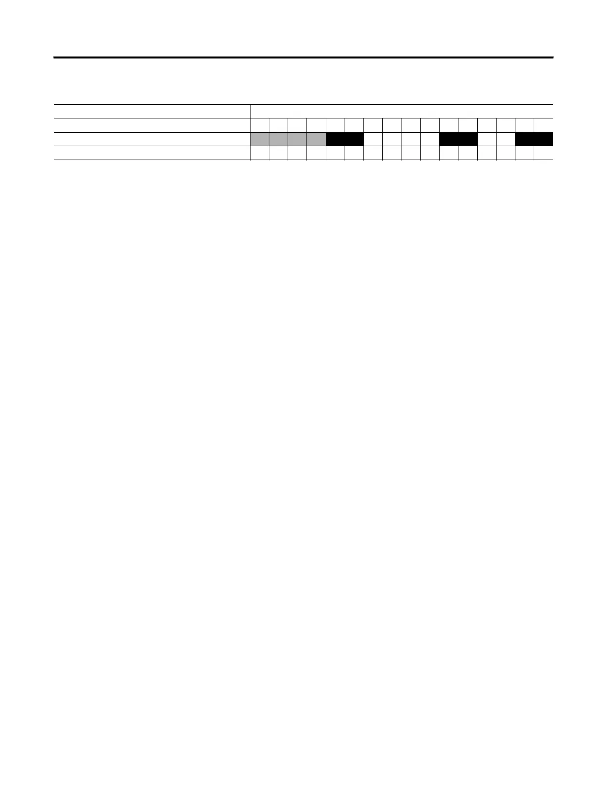
The outputs shown in the black boxes are the outputs under the control
of the HSC sub-system. The mask defines which outputs can be
controlled. The high preset output or low preset output values (HPO or
LPO) define if each output is either ON (1) or OFF (0). Another way to
view this is that the high or low preset output is written through the
output mask, with the output mask acting like a filter.
The bits in the gray boxes are unused. The first 6 bits of the mask word
are used and the remaining mask bits are not functional because they do
not correlate to any physical outputs on the base unit.
The mask bit pattern can be configured only during initial setup.
O0:0.0 0 1 0 1 0 1
Affect of HSC Output Mask on Base Unit Outputs
Output Address 16-Bit Signed Integer Data Word
1514131211109876543210
efesotomasyon.com - Allen Bradley,Rockwell,plc,servo,drive

 Loading...


