EasyManuals Logo

Allen-Bradley MicroLogix 1400 User Manual

Allen-Bradley MicroLogix 1400
694 pages
To Next Page IconTo Next Page
To Previous Page IconTo Previous Page
Page #144 background imageLoading...
Page #144 background image
Publication 1766-RM001A-EN-P - October 2008
142 Using High-Speed Outputs
structure of the control program determines when the DN bit goes off. So,
to detect when the PTO instruction completes its output, you can monitor
the Done (DN), Idle (ID), or Normal Operation (NO) status bits.
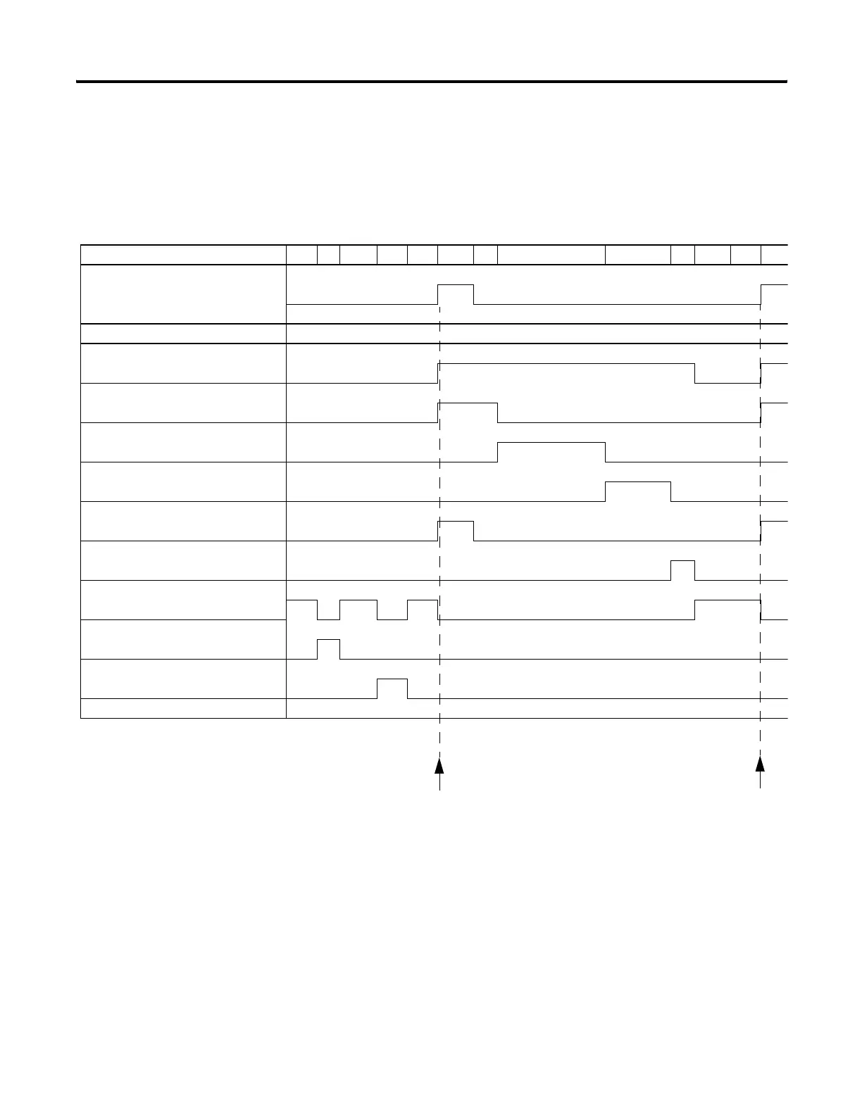
Standard Logic Enable Example
In this example, the rung state is a maintained type of input. This means
that it enables the PTO instruction Normal Operation (NO) and maintains
its logic state until after the PTO instruction completes its operation. With
this type of logic, status bit behavior is as follows:
Stage 0 1 2 3 4 5 6 7 8 9 10 11 12
Rung State
Sub-Elements: Relative Timing
Normal Operation/NO
Accelerate Status/AS
Run Status/RS
Decelerate Status/DS
Enable/EN
Done/DN
Idle/ID
Jog Pulse/JP
Jog Continuous/JC
Start of PTO
Start of PTO
efesotomasyon.com - Allen Bradley,Rockwell,plc,servo,drive

Table of Contents

Other manuals for Allen-Bradley MicroLogix 1400

Questions and Answers:

Question and Answer IconNeed help?

Do you have a question about the Allen-Bradley MicroLogix 1400 and is the answer not in the manual?

Allen-Bradley MicroLogix 1400 Specifications

General IconGeneral
Processor32-bit
Expansion ModulesUp to 7 expansion I/O modules
Power Supply24V DC or 120/240V AC
Programming SoftwareRSLogix 500
Communication PortsEthernet, RS-232/RS-485 combo port
Controller TypeProgrammable Logic Controller (PLC)
SeriesMicroLogix
Digital Outputs12
Analog Inputs6 (embedded)
Analog Outputs2 (embedded)
High-Speed Counter6 high-speed counters
Pulse Output2 (embedded)
Ethernet PortYes

Related product manuals