Publication 1766-RM001A-EN-P - October 2008
166 Using High-Speed Outputs
PWMX Accel/Decel Delay (ADD)
PWMX ADD (Accel/Decel Delay) defines the amount of time in 10
millisecond interval to ramp from zero to 20kHz frequency. Also specifies
the time to ramp down to zero.
The PWMX ADD value is loaded and activated immediately (whenever
the PWM instruction is scanned on a true rung of logic). This allows
multiple steps or stages of acceleration or deceleration to occur.
PWMX Error Code (ER)
PWMX ER (Error Codes) detected by the PWM sub-system are displayed
in this register. The table identifies known errors.
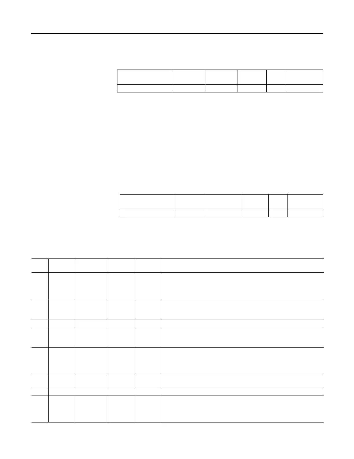
Element Description Address Data Format Range Type User Program
Access
ADD - Accel/Decel Delay PWMX:0.ADD word (INT) 0…32,767 control read/write
Element Description Address Data Format Range Type User Program
Access
ER - PWM Error Codes PWMX:0.ER word (INT) -2…5 status read only
Error
Code
Non-User
Fault
Recoverable
Fault
Instruction
Errors
Error
Name
Description
-2 Yes No No Overlap
Error
An output overlap is detected. Multiple functions are assigned to the same
physical output. This is a configuration error. The controller faults and the
User Fault Routine does not execute. Example: PWM0 and PWM1 are both
attempting to use a single output.
-1 Yes No No Output
Error
An invalid output has been specified. Output 2, output 3, and output 4 are the
only valid choices. This is a configuration error. The controller faults and the
User Fault Routine does not execute.
0 Normal Normal (0 = no error present)
1 No No Yes Hardstop
Error
This error is generated whenever a hardstop is detected. This error does not
fault the controller. It is automatically cleared when the hardstop condition is
removed.
2 No No Yes Output
Forced
Error
The configured PWM output (2, 3, or 4) is currently forced. The forced
condition must be removed for the PWM to operate. This error does not fault
the controller. It is automatically cleared when the force condition is
removed.
3 Yes Yes No Frequency
Error
The frequency value is less than 0 or greater than 40,000. This error faults
the controller. It can be cleared by logic within the User Fault Routine.
4Reserved
5 Yes Yes No Duty Cycle
Error
The PWM duty cycle is either less than zero or greater than 1000.
This error faults the controller. It can be cleared by logic within the User Fault
Routine.
efesotomasyon.com - Allen Bradley,Rockwell,plc,servo,drive

 Loading...


