Publication 1766-RM001A-EN-P - October 2008
24 I/O Configuration
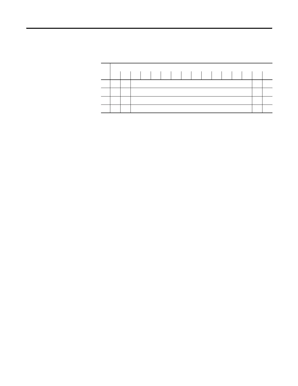
Words 0…3 contain the analog output data for channels 0…3,
respectively. The module ignores the “don’t care” bits (0 and 1), but
checks the sign bit (15), and bit 14. If bit 15 equals one, the module sets
the output value to 0V or 0 mA. If bit 15 equals zero and bit 14 equals
one, the module sets the output value to 10.5V DC or 21 mA.
Scaled-for-PID Format
Word
Bit Position
1514131211109876543210
0 0 0 Channel 0 Data 0 to 16,380 0 0
1 0 0 Channel 1 Data 0 to 16,380 0 0
2 0 0 Channel 2 Data 0 to 16,380 0 0
3 0 0 Channel 3 Data 0 to 16,380 0 0
efesotomasyon.com - Allen Bradley,Rockwell,plc,servo,drive

 Loading...


