Publication 1766-RM001A-EN-P - October 2008
Conversion Instructions 247
• 32768 if the source is the math register (allowing a 5-digit BCD value
with the lower 4 digits stored in S:13 and the high order digit in
S:14).
If the source is the math register, it must be directly addressed as S:13.
S:13 is the only status file element that can be used.
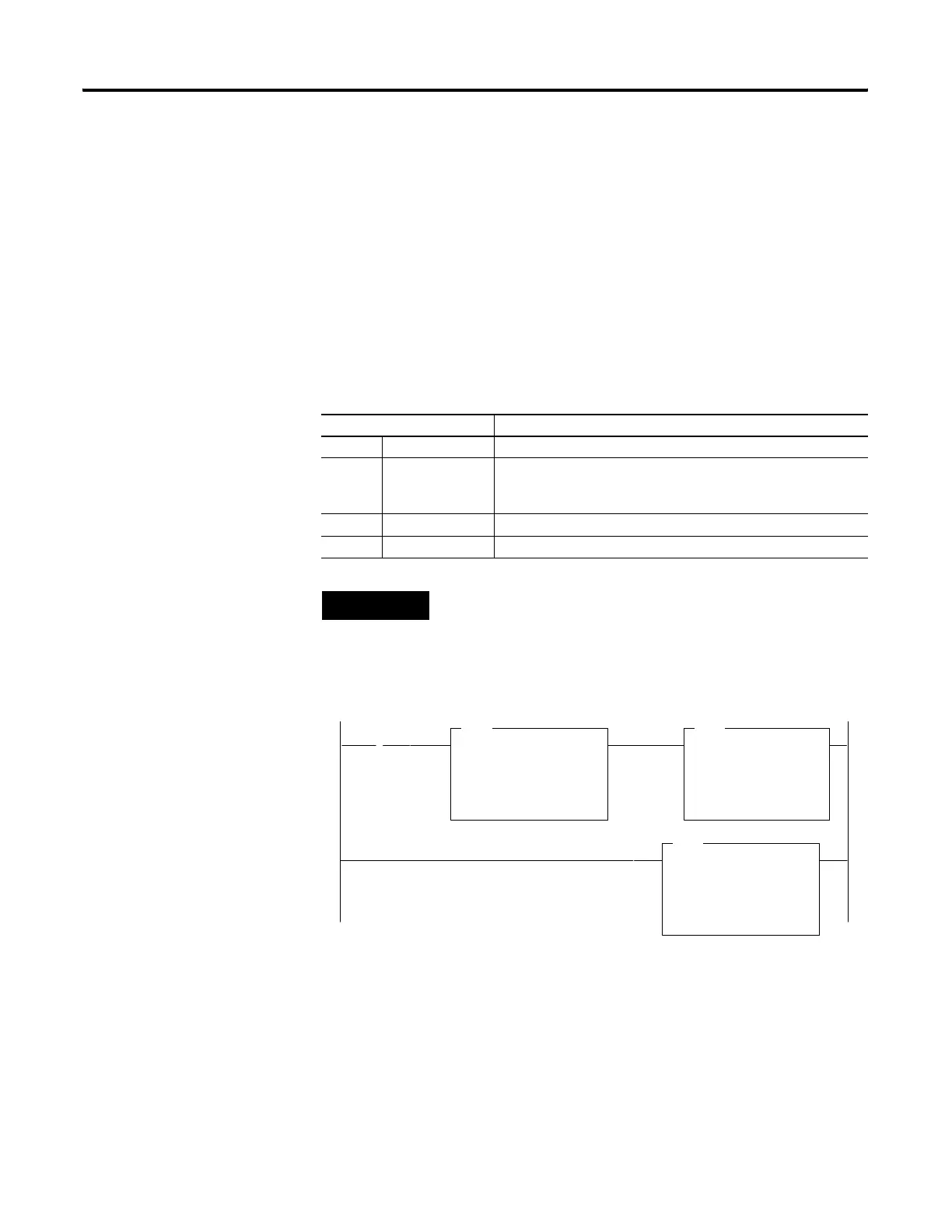
Updates to Math Status Bits
The two rungs shown cause the controller to verify that the value I:0
remains the same for two consecutive scans before it executes the FRD.
This prevents the FRD from converting a non-BCD value during an input
value change.
Math Status Bits
With this Bit: The Controller:
S:0/0 Carry always resets
S:0/1 Overflow sets if non-BCD value is contained at the source or the value to be
converted is greater than 32,767; otherwise resets. On overflow,
the minor error flag is also set.
S:0/2 Zero Bit sets if result is zero, otherwise resets
S:0/3 Sign Bit always resets
TIP
Always provide ladder logic filtering of all BCD input devices prior to
performing the FRD instruction. The slightest difference in point-to-point
input filter delay can cause the FRD instruction to overflow due to the
conversion of a non-BCD digit.
]/[
S:1
15
EQU
EQUAL
Source A N7:1
0
Source B I:0.0
0
MOV
MOVE
Source I:0.0
0
Dest N7:1
0
FRD
FROM BCD
Source I:0.0
0
Dest N7:2
0
efesotomasyon.com - Allen Bradley,Rockwell,plc,servo,drive

 Loading...


