EasyManuals Logo

Allen-Bradley MicroLogix 1400 User Manual

Allen-Bradley MicroLogix 1400
694 pages
To Next Page IconTo Next Page
To Previous Page IconTo Previous Page
Page #251 background imageLoading...
Page #251 background image
Publication 1766-RM001A-EN-P - October 2008
Conversion Instructions 249
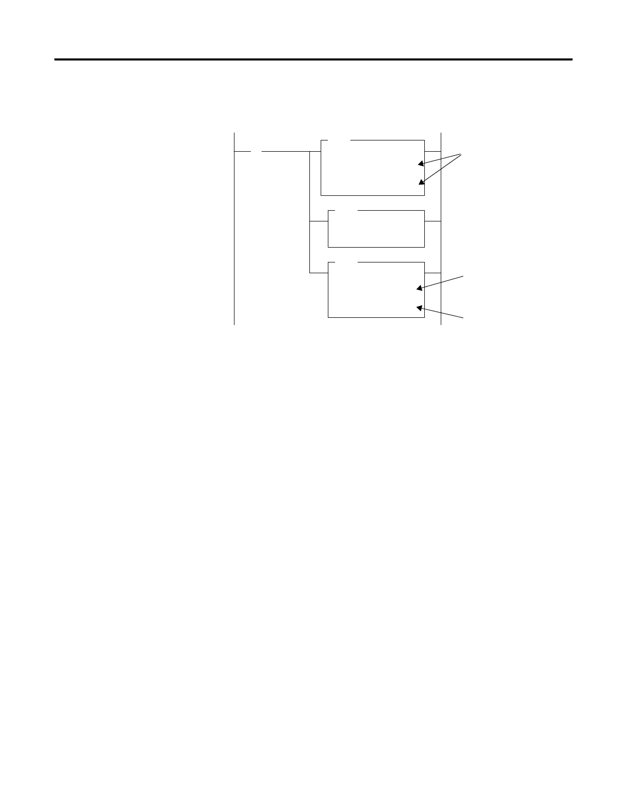
Clearing S:14 before executing the FRD instruction is shown below:
When the input condition I:0/1 is set (1), a BCD value (transferred from a
4-digit thumbwheel switch for example) is moved from word N7:2 into
the math register. Status word S:14 is then cleared to make certain that
unwanted data is not present when the FRD instruction is executed.
CLR
CLEAR
Dest S:14
0
FRD
FROM BCD
Source S:13
00001234
Dest N7:0
1234
MOV
MOVE
Source N7:2
4660
Dest S:13
4660
] [
I:1
0
0001 0010 0011 0100
0000 0100 1101 0010
S:13 and S:14 are
displayed in BCD format.
efesotomasyon.com - Allen Bradley,Rockwell,plc,servo,drive

Table of Contents

Other manuals for Allen-Bradley MicroLogix 1400

Questions and Answers:

Question and Answer IconNeed help?

Do you have a question about the Allen-Bradley MicroLogix 1400 and is the answer not in the manual?

Allen-Bradley MicroLogix 1400 Specifications

General IconGeneral
Processor32-bit
Expansion ModulesUp to 7 expansion I/O modules
Power Supply24V DC or 120/240V AC
Programming SoftwareRSLogix 500
Communication PortsEthernet, RS-232/RS-485 combo port
Controller TypeProgrammable Logic Controller (PLC)
SeriesMicroLogix
Digital Outputs12
Analog Inputs6 (embedded)
Analog Outputs2 (embedded)
High-Speed Counter6 high-speed counters
Pulse Output2 (embedded)
Ethernet PortYes

Related product manuals