Publication 1766-RM001A-EN-P - October 2008
Sequencer Instructions 293
This instruction uses the following operands:
• File - This is the sequencer reference file. Its contents, on an
element-by-element, basis are masked and stored in the destination.
• Mask - The mask operand contains the mask value. When mask bits
are set to 1, data is allowed to pass through to destination. When
mask bits are reset to 0, the data is masked (does not pass through
to destination). The immediate data ranges for mask are from
0…0xFFFF (word) or 0…0xFFFFFFFF (long word).
• Destination - The destination operand is the sequencer location or
file.
• Control - This is a control file address. The status bits, stack length,
and the position value are stored in this element. The control
element consists of 3 words:
• Length - The length operand contains the number of steps in the
sequencer file (as well as Mask and/or Destination if they are file
data types). The length of the sequencer can range from 1…256.
• Position - This is the current location or step in the sequencer file
(as well as Mask and/or Destination if they are file data types). It
determines the next location in the stack to be masked and moved
to the destination. Position is a component of the control register.
The position can range from 0…255. Position is incremented on
each false-to-true transition.
TIP
If file type is word, then mask and source must be words. If file type is
long word, mask and source must be long words.
TIP
If mask is direct or indirect, the position selects the location in the
specified file.
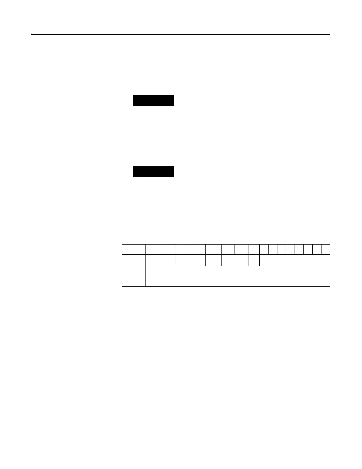
15 1413 1211 10 9 8 76543210
Word 0
EN
(1)
(1) EN - Enable Bit is set by a false-to-true rung transition and indicates that the instruction is enabled.
--
DN
(2)
(2) DN - Done Bit is set after the instruction has operated on the last word in the sequencer file. It is reset on the next
false-to-true rung transition after the rung goes false.
--
ER
(3)
(3) ER - Error Bit is set when the controller detects a negative position value, or a negative or zero length value. When the
ER bit is set, the minor error bit (S2:5/2) is also set.
not used FD not used
Word 1 Length - contains the index of the last element in the sequencer reference file
Word 2 Position - the current position in the sequence
efesotomasyon.com - Allen Bradley,Rockwell,plc,servo,drive

 Loading...


