EasyManuals Logo

Allen-Bradley MicroLogix 1400 User Manual

Allen-Bradley MicroLogix 1400
694 pages
To Next Page IconTo Next Page
To Previous Page IconTo Previous Page
Page #41 background imageLoading...
Page #41 background image
Publication 1766-RM001A-EN-P - October 2008
Controller Memory and File Types 41
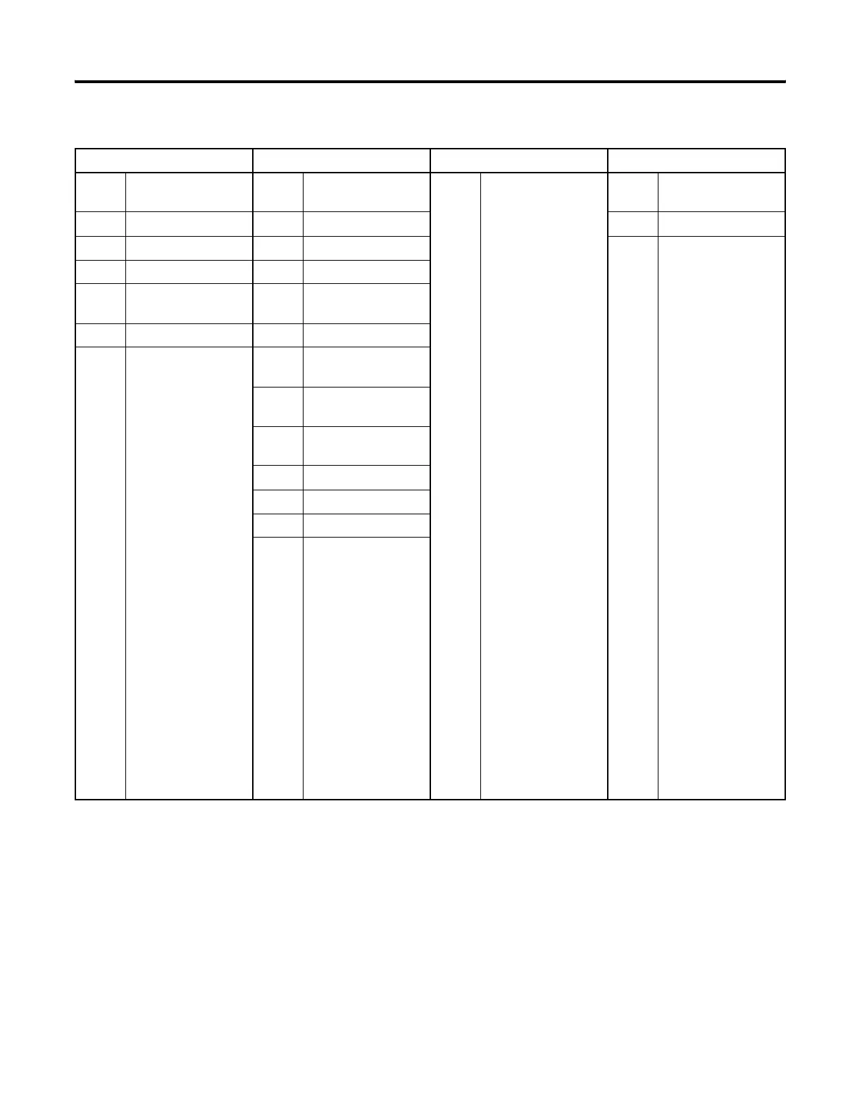
3 Bit File STI Selectable Timed
Interrupt
3…255 Program Files 3…255 0 Recipe File 0
4 Timer File EII Event Input Interrupt 1 Recipe File 1
5 Counter File RTC Real Time Clock 2…255 Recipe Files 2…255
6 Control File
7 Integer File MMI Memory Module
Information
8 Floating Point File
9…255 (B) Bit
(T) Timer
(C) Counter
(R) Control
(N) Integer
(F) Floating Point
(ST) String
(A) ASCII
(L) Long Word
(MG) Message
(PD) PID
(PLS) Programmable
Limit Switch
(RI) Routing
Information
(RIX) Extended Routing
Information
BHI Base Hardware
Information
CS0 Communications
Status for Channel 0
CS2 Communications
Status for Channel 2
IOS I/O Status
DLS Data Log Status
LCD LCD
ES1 Ethernet Status for
Channel 1
Controller User Memory File Types
Data Files Function Files Program Files Specialty Files
efesotomasyon.com - Allen Bradley,Rockwell,plc,servo,drive

Table of Contents

Other manuals for Allen-Bradley MicroLogix 1400

Questions and Answers:

Question and Answer IconNeed help?

Do you have a question about the Allen-Bradley MicroLogix 1400 and is the answer not in the manual?

Allen-Bradley MicroLogix 1400 Specifications

General IconGeneral
Processor32-bit
Expansion ModulesUp to 7 expansion I/O modules
Power Supply24V DC or 120/240V AC
Programming SoftwareRSLogix 500
Communication PortsEthernet, RS-232/RS-485 combo port
Controller TypeProgrammable Logic Controller (PLC)
SeriesMicroLogix
Digital Outputs12
Analog Inputs6 (embedded)
Analog Outputs2 (embedded)
High-Speed Counter6 high-speed counters
Pulse Output2 (embedded)
Ethernet PortYes

Related product manuals