Publication 1766-RM001A-EN-P - October 2008
418 Communications Instructions
Data Table Address
This variable defines the starting address in the local controller. Valid file
types for the Data Table Address are shown below:
Size in Elements
This variable defines the amount of data (in elements) to exchange with
the target device.
The maximum amount of data that can be transferred via a MSG
instruction is 103 words (120 words for Modbus commands) and is
determined by the destination data type. The destination data type is
defined by the type of message: read or write.
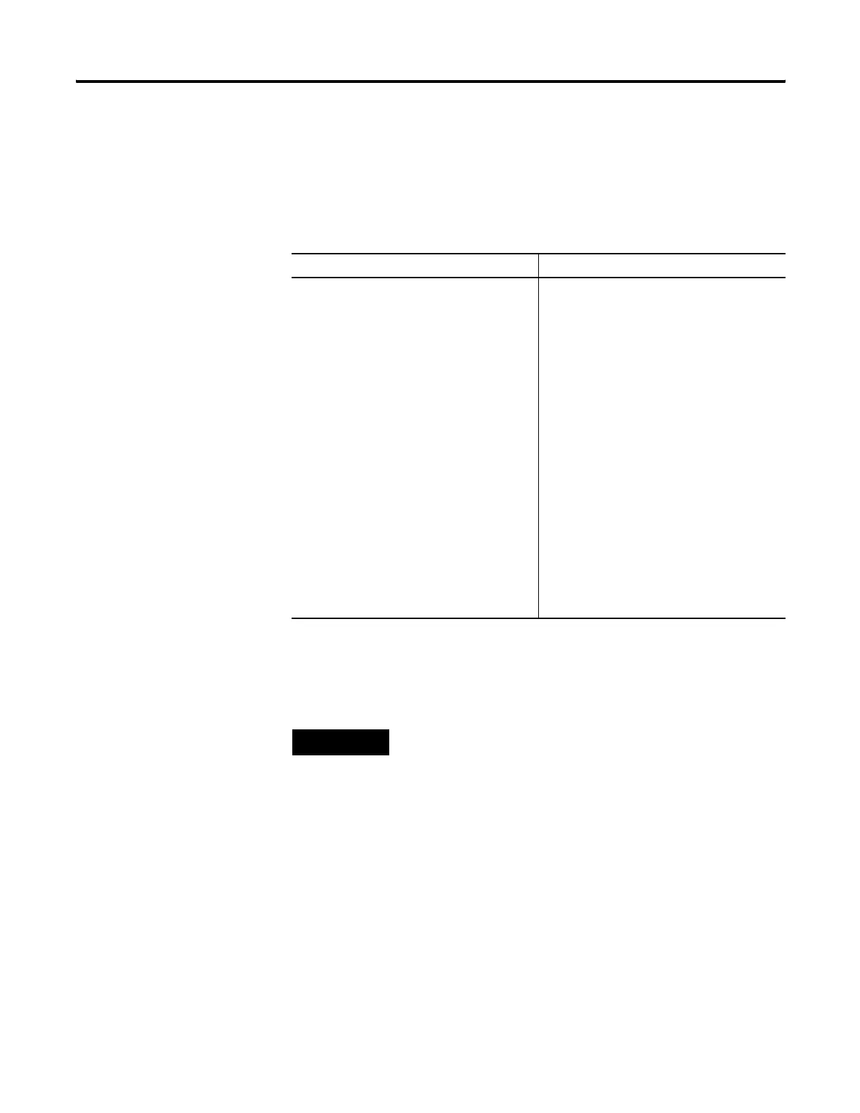
Message Read Message Write
Bit (B)
Timer (T)
Counter (C)
Control (R)
Integer (N)
Floating Point (F)
(1)
Long Word (L)
String (ST)
(1) Message Type must be 500CPU or PLC5. The Local File Type and Target File Type must both be Floating Point.
Output (O)
Input (I)
Bit (B)
Timer (T)
Counter (C)
Control (R)
Integer (N)
Floating Point (F)
(1)
Long Word (L)
String (ST)
Real-Time Clock (RTC)
(2)
(2) 500CPU write RTC-to-Integer or RTC-to-RTC only.
TIP
Only Bit (B) and Integer (N) file types are valid for Modbus Command
messages. Modbus bit commands require a starting bit address for the
Data Table Address.
Floating Point (F) and Long (L) file types are valid for Modbus Command
messages for Holding Registers (commands 03, 06 and 16) when Data is
configured for 32 bit.
efesotomasyon.com - Allen Bradley,Rockwell,plc,servo,drive

 Loading...


