Publication 1766-RM001A-EN-P - October 2008
422 Communications Instructions
Data Table Address/Offset
This variable defines the starting address in the target controller. The data
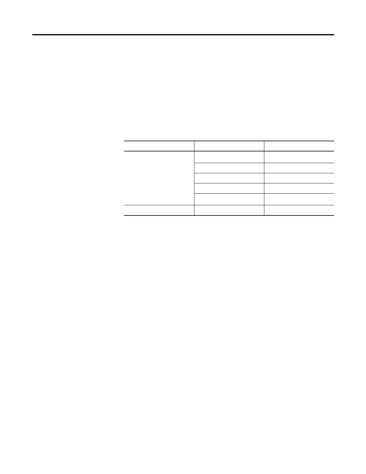
table address is used for a 500CPU and PLC5 type messages. A valid
address is any valid, configured data file within the target device whose
file type is recognized by the controller. Valid combinations are shown
below:
The data table offset is used for 485CIF type messages. A valid offset is
any value in the range 0…255 and indicates the word or byte offset into
the target's Common Interface File (CIF). The type of device determines
whether it is a word or byte offset. MicroLogix controllers and SLC
processors use word offset; PLC-5 and Logix processors use byte offset.
Modbus - MB Data Address (1-65536)
Modbus addressing is limited to 16 bits per memory group, each with a
range of 1…65,536. There are four memory groups, one for each function:
• coils (generally addressed as 0xxxx)
• contacts (1xxxx)
• input registers (3xxxx)
• holding registers (4xxxx)
Coils and contacts are addressed at the bit level. Coils are outputs and can
be read and written. Contacts are inputs and are read-only.
Input registers and holding registers are addressed at the word level.
Input registers are generally used for internally storing input values. They
are read-only. Holding registers are general purpose and can be both read
and written.
Message Type Local File Type Target File Type
500CPU and PLC5
O, I, B, N, F
(1)
, L
(1) Message Type must be 500CPU or PLC5. The Local File Type and Target File Type must both be Floating Point.
O, I, S, B, N, F
(1)
, L
TT
CC
RR
RTC
(2)
(2) 500CPU write RTC-to-Integer or RTC-to-RTC only.
N, RTC
500CPU, PLC5 and 485 CIF ST ST
efesotomasyon.com - Allen Bradley,Rockwell,plc,servo,drive

 Loading...


