EasyManuals Logo

Allen-Bradley MicroLogix 1400 User Manual

Allen-Bradley MicroLogix 1400
694 pages
To Next Page IconTo Next Page
To Previous Page IconTo Previous Page
Page #448 background imageLoading...
Page #448 background image
Publication 1766-RM001A-EN-P - October 2008
446 Communications Instructions
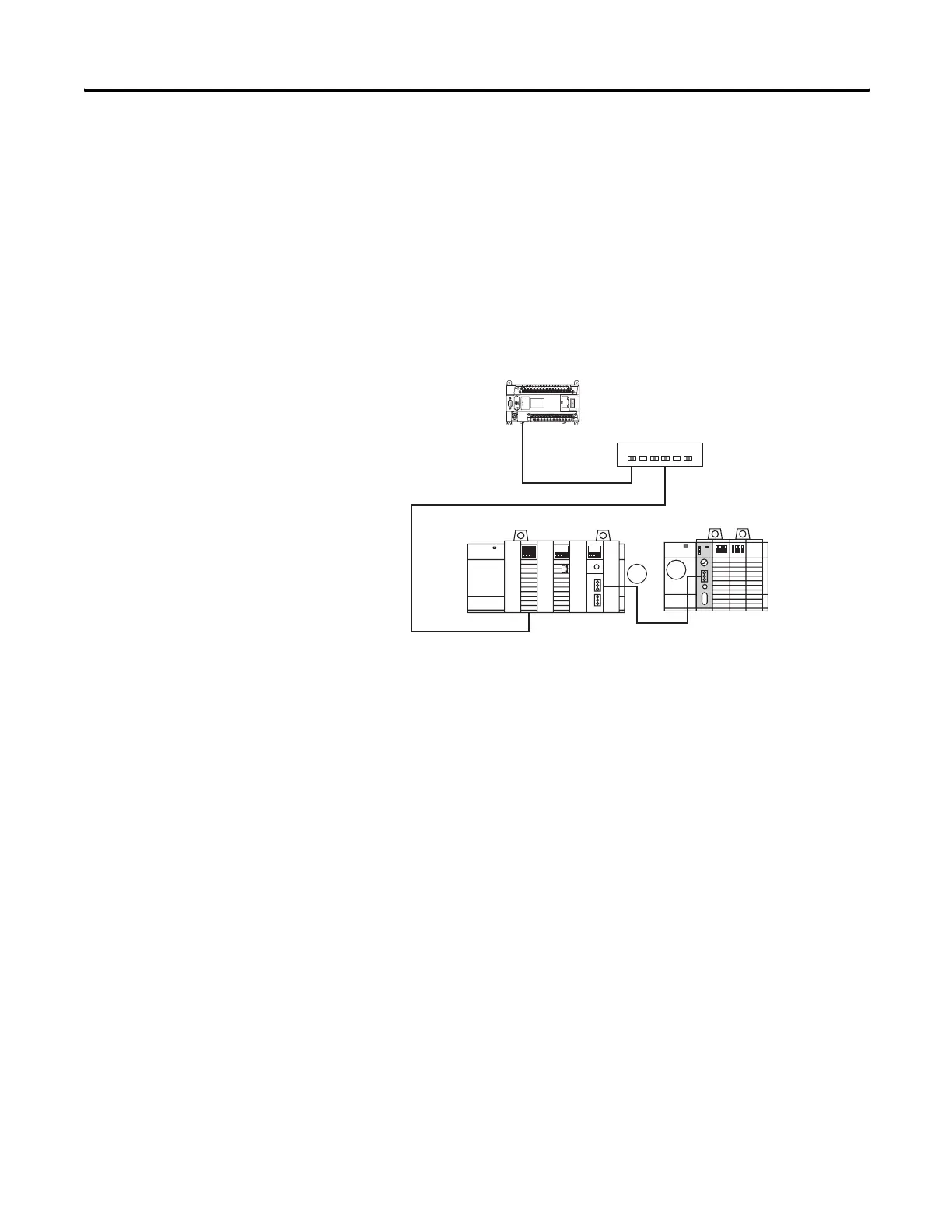
Network Message Example 1:
MicroLogix 1400 Ethernet to SLC5/04 DH+ via ENET & DHRIO
The following illustrates the MicroLogix 1400 (CH1 Ethernet) sending a
remote message to a SLC5/04 processor (DH+ Node 51). The remote
message will s an ENET module, a ControlLogix chassis (Gateway) and a
DHRIO module. In order for the message to pass through the network, a
MultiHop MSG must be setup and a DHRIO Routing table must exist.
Belden 9463 "Blue Hose" cable is used to connect the DH+ devices on the
network. Ethernet cable and an Ethernet hub are used to connect the
ENET module and the MicroLogix 1400 CH1 Ethernet ports together.
Ethernet Hub
100.100.115.1
Control Logix Gateway
Backplane
Link ID 20
SLC5/04
DHRIO Link ID 24
100.100.115.7
Link ID 16
Link
ID 7
1
Link
ID 7
A
B
51
MicroLogix 1400
44589
efesotomasyon.com - Allen Bradley,Rockwell,plc,servo,drive

Table of Contents

Other manuals for Allen-Bradley MicroLogix 1400

Questions and Answers:

Question and Answer IconNeed help?

Do you have a question about the Allen-Bradley MicroLogix 1400 and is the answer not in the manual?

Allen-Bradley MicroLogix 1400 Specifications

General IconGeneral
Processor32-bit
Expansion ModulesUp to 7 expansion I/O modules
Power Supply24V DC or 120/240V AC
Programming SoftwareRSLogix 500
Communication PortsEthernet, RS-232/RS-485 combo port
Controller TypeProgrammable Logic Controller (PLC)
SeriesMicroLogix
Digital Outputs12
Analog Inputs6 (embedded)
Analog Outputs2 (embedded)
High-Speed Counter6 high-speed counters
Pulse Output2 (embedded)
Ethernet PortYes

Related product manuals