EasyManuals Logo

Allen-Bradley MicroLogix 1400 User Manual

Allen-Bradley MicroLogix 1400
694 pages
To Next Page IconTo Next Page
To Previous Page IconTo Previous Page
Page #451 background imageLoading...
Page #451 background image
Publication 1766-RM001A-EN-P - October 2008
Communications Instructions 449
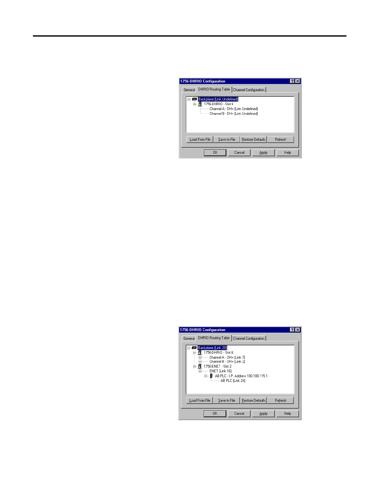
Select DHRIO Routing Table tab. If no routing table has been created the
following should appear.
Right click on the Backplane and left click on Edit Module. Make sure that
the Back plane Link ID is set to 20.
Right click on the 1756-DHRIO module and left click on Edit Module.
Make sure that CH A's Link ID is set for 7 and CH B's Link ID is set for 2.
Select OK. Channel B is actually not necessary.
Right click on the Backplane and left click on Add Module. Left click on
1756-ENET.
Enter the correct slot number 2 and Link ID 16 for the ENET module.
Right click on the 1756-ENET Link ID and left click on Add Module. Left
click on AB PLC.
Enter the IP address (100.100.115.1) for the destination Ethernet processor
and its Link ID (24).
The Configuration should now look like the following.
efesotomasyon.com - Allen Bradley,Rockwell,plc,servo,drive

Table of Contents

Other manuals for Allen-Bradley MicroLogix 1400

Questions and Answers:

Question and Answer IconNeed help?

Do you have a question about the Allen-Bradley MicroLogix 1400 and is the answer not in the manual?

Allen-Bradley MicroLogix 1400 Specifications

General IconGeneral
Processor32-bit
Expansion ModulesUp to 7 expansion I/O modules
Power Supply24V DC or 120/240V AC
Programming SoftwareRSLogix 500
Communication PortsEthernet, RS-232/RS-485 combo port
Controller TypeProgrammable Logic Controller (PLC)
SeriesMicroLogix
Digital Outputs12
Analog Inputs6 (embedded)
Analog Outputs2 (embedded)
High-Speed Counter6 high-speed counters
Pulse Output2 (embedded)
Ethernet PortYes

Related product manuals