Publication 1766-RM001A-EN-P - October 2008
564 System Status File
Memory Module Boot
When this bit is set (1) by the controller, it indicates that a memory
module program has been transferred due to S:1/10 (Load Memory
Module on Error or Default Program) or S:1/11 (Load Memory Module
Always) being set in an attached memory module user program. This bit
is not cleared (0) by the controller.
Your program can examine the state of this bit on the first scan (using bit
S:1/15) on entry into an Executing mode to determine if the memory
module user program has been transferred after a power-up occurred.
This information is useful when you have an application that contains
retentive data and a memory module has bit S:1/10 or bit S:1/11 set.
Memory Module Password Mismatch
At power-up, if Load Always is set, and the controller and memory
module passwords do not match, the Memory Module Password
Mismatch bit is set (1).
SeePassword Protection on page 50 for more information.
STI Lost
This address is duplicated at STI:0/UIL. SeeUsing the Selectable Timed
Interrupt (STI) Function File on page 318 for more information.
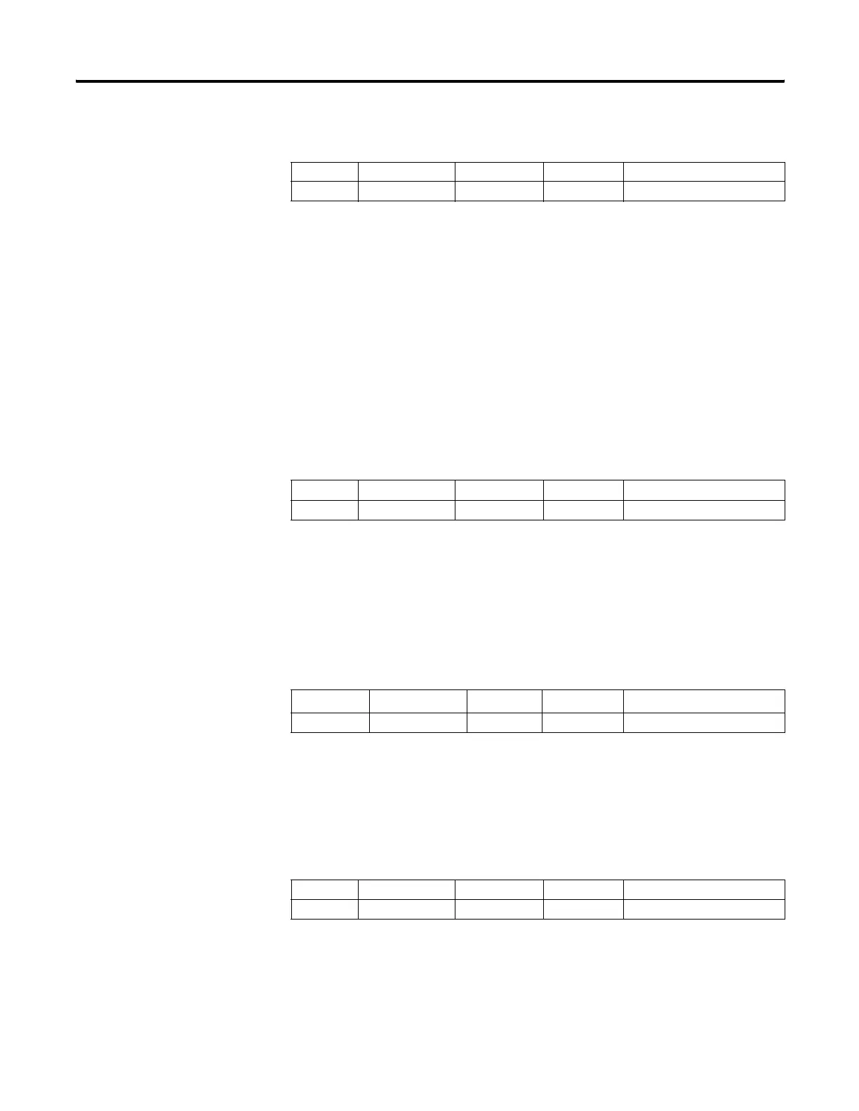
Processor Battery Low
This bit is set (1) when the battery is low.
Address Data Format Range Type User Program Access
S:5/8 binary 0 or 1 status read/write
Address Data Format Range Type User Program Access
S:5/9 binary 0 or 1 status read/write
Address
(1)
(1) This bit can only be accessed via ladder logic. It cannot be accessed via communications (such as a Message
instruction from another device).
Data Format Range Type User Program Access
S:5/10 binary 0 or 1 status read/write
Address Data Format Range Type User Program Access
S:5/11 binary 0 or 1 status read only
efesotomasyon.com - Allen Bradley,Rockwell,plc,servo,drive

 Loading...


