Product description
36
UF 01 DB 238. 07.04
Function
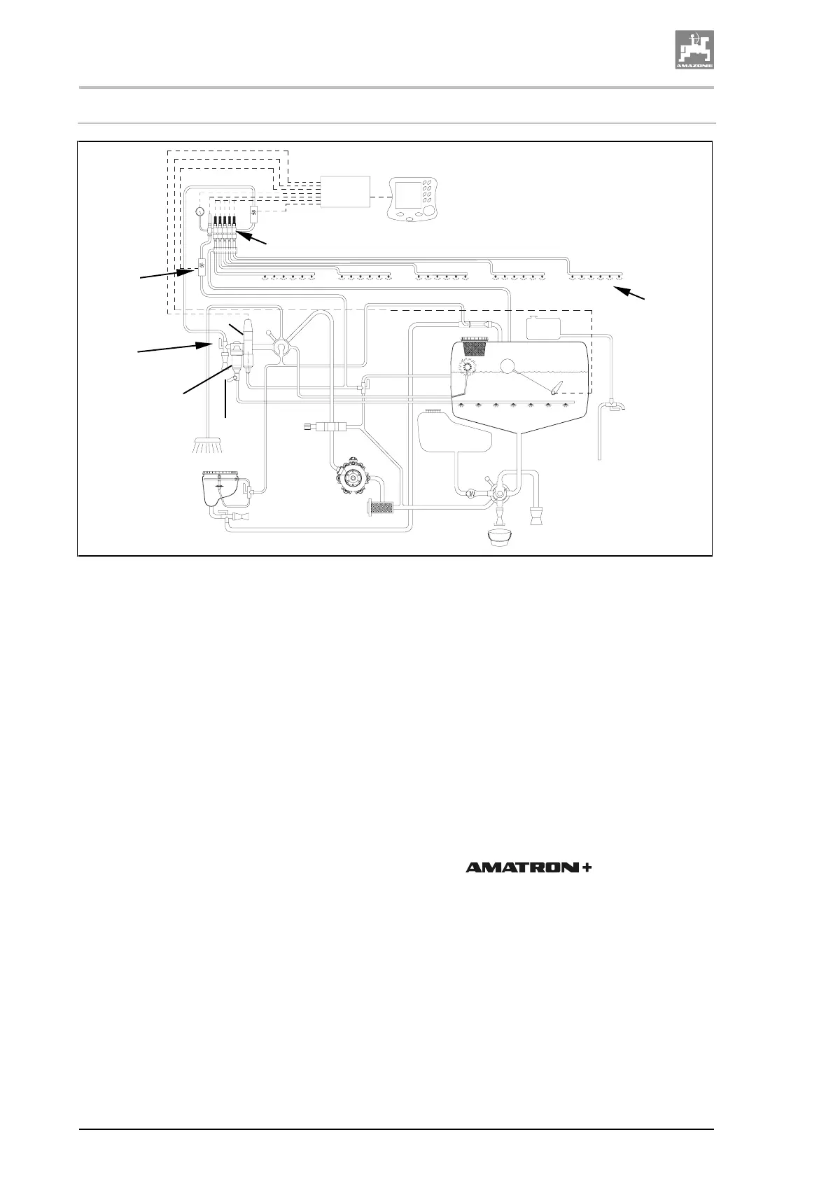
Fig. 6
The piston diaphragm pump (1) sucks the spray cocktail via the
VARIO-control-suction side (2), the suction hose (3) and the suction
filter (4) off the spray cocktail tank (5). The sucked spray cocktail is
delivered via the pressure hose (6) to the VARIO-control-pressure
side (7). Via the VARIO-control-pressure side (7) the spray cocktail
gets into the pressure device (8). The pressure device (8) consists of
the spray pressure-control (9) and the self cleaning pressure filter
(10). With the aid of the pressure device (8) the spray cocktail is de-
livered via the flow meter (11) to the boom part section valves (12).
The boom part width section valves (12) distribute the spray cocktail
to the individual spray lines (13). At small spray rates, the return flow
meter (14) determines the spray cocktail amount which is returned
into the spray cocktail tank (5).
The agitator (15) being switched on provides a homogeneous spray
cocktail in the spray cocktail tank (5). The agitation intensity can be
set in 6 steps at the step tap (16).
Entry on the operator terminal
(17)
• implement specific data.
• implement order related data.
• access of the field sprayer to change the spray rate during
spraying operation.
• control of all functions on the sprayer booms.
• control of special functions.
• monitoring the field sprayer during the spraying operation.
For preparing the spray cocktail fill the required agent quantity for one
spray cocktail tank filling into the induction bowl (18) and suck it into
the spray cocktail tank (5).
The clean water in the clean water tank (19) is used for cleaning the
spraying system.
1
2
3
4
5
6
7
8
9
10
11
12
13
14
15
16
17
18
19



 To Next Page