Table of contents
6
UF 01 DB 238. 07.04
4 Assembly and function..............................................................................44
4.1 Tank level indicator................................................................................................................44
4.2 Agitation .................................................................................................................................44
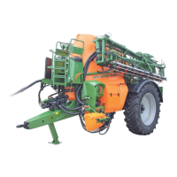
4.3 Pump equipment....................................................................................................................45
4.4 Filter equipment .....................................................................................................................46
4.4.1 Filling sieve ............................................................................................................................46
4.4.2 Suction filter ...........................................................................................................................46
4.4.3 Self cleaning pressure filter....................................................................................................47
4.4.4 Nozzle filter up to ...................................................................................................................48
4.4.5 Bottom sieve in the induction bowl ........................................................................................48
4.4.6 Urea filter................................................................................................................................49
4.5 Clean water tank ....................................................................................................................49
4.6 Induction bowl with injector and canister flushing..................................................................50
4.7 Hand washing tank ................................................................................................................51
4.8 Ladder....................................................................................................................................52
4.9 Operator terminal .................................................................................53
4.9.1 Hierarchy of ..........................................................................................54
4.9.2 Description of operator terminal.............................................................................................55
4.9.2.1 Display and function keys ......................................................................................................55
4.9.2.2 Keys on the implement front side...........................................................................................56
4.9.2.3 Keys on implement rear side .................................................................................................57
4.9.3 switch on................................................................................................57
4.9.4 Inputs on ...............................................................................................58
4.9.4.1 Entering of text and figures....................................................................................................59
4.9.4.2 Selection of options................................................................................................................59
4.9.4.3 Switching on/off of functions (Toggle function)......................................................................60
4.9.5 Main menu .............................................................................................................................60
4.9.6 Menu order.............................................................................................................................61
4.9.6.1 Create order / start or recall stored order data ......................................................................61
4.9.7 Menu implement data ............................................................................................................62
4.9.7.1 Calibration of tilt adjustment...................................................................................................64
4.9.7.2 Impulses per litre....................................................................................................................65
4.9.7.2.1 Determine the Impulses per litre - Flow meter.......................................................................66
4.9.7.2.2 Manually enter the Impulses per litre - Flow meter................................................................66
4.9.7.2.3 Align return flow meter with flow meter..................................................................................67
4.9.7.2.4 Manually enter impulses per litre – return flow meter............................................................68
4.9.7.3 Nominal PTO shaft rev. speed...............................................................................................68
4.9.7.3.1 Enter the nominal PTO shaft rev. speed................................................................................68
4.9.7.3.2 Enter the impulses per PTO shaft rev....................................................................................69
4.9.7.3.3 Storage of the nominal PTO shaft speeds for different tractors ............................................69
4.9.7.3.4 Storage of the impulses per PTO shaft rev. for different tractors ..........................................70
4.9.7.3.5 Storage of the alarm limit for the nominal PTO shaft rev. speed...........................................71
4.9.7.4 Impulses per 100m ................................................................................................................72
4.9.7.4.1 Manual entering of impulses per 100m..................................................................................73
4.9.7.4.2 Determination of impulses per 100m via a calibration travel.................................................73
4.9.7.5 Storage of impulses per 100m for different tractors...............................................................74
4.9.7.6 Permanently switch on / off the boom part width sections.....................................................74
4.9.7.7 Explanations for the function "Selection of individual boom sections"...................................75
4.9.7.8 Refill spray cocktail tank with water .......................................................................................76
4.9.8 Menu setup ............................................................................................................................78
4.9.8.1 Entering simulated speed (in case of defect distance sensor) ..............................................79
4.9.8.2 Entering machine basic data..................................................................................................80
4.9.8.2.1 Selection of machine type......................................................................................................82
4.9.8.2.2 Selection of the boom folding.................................................................................................82
4.9.8.2.3 Configuration of the tank filling level indicator .......................................................................83
4.9.8.2.4 Calibration filling level indicator .............................................................................................83
4.9.8.2.5 Enter nozzles per boom part section .....................................................................................83
4.9.8.2.6 Terminal-Setup ......................................................................................................................84
 Loading...