PN 903-8797, Rev A
From the Filterblock Assembly, the gas passes through a Flow Restrictor and
then through a ame arrestor before entering the Measuring Cell, where the
sample is measured using the chilled-mirror technique. It then leaves the Cell
and passes through another ame arrestor, a pressure regulator, and a 1 PSIG
check valve on its way back to the Filterblock Assembly and then to the Vent
Line, which vents the used sample gas to atmosphere or to an approved low
pressure (<50 PSIG) are header.
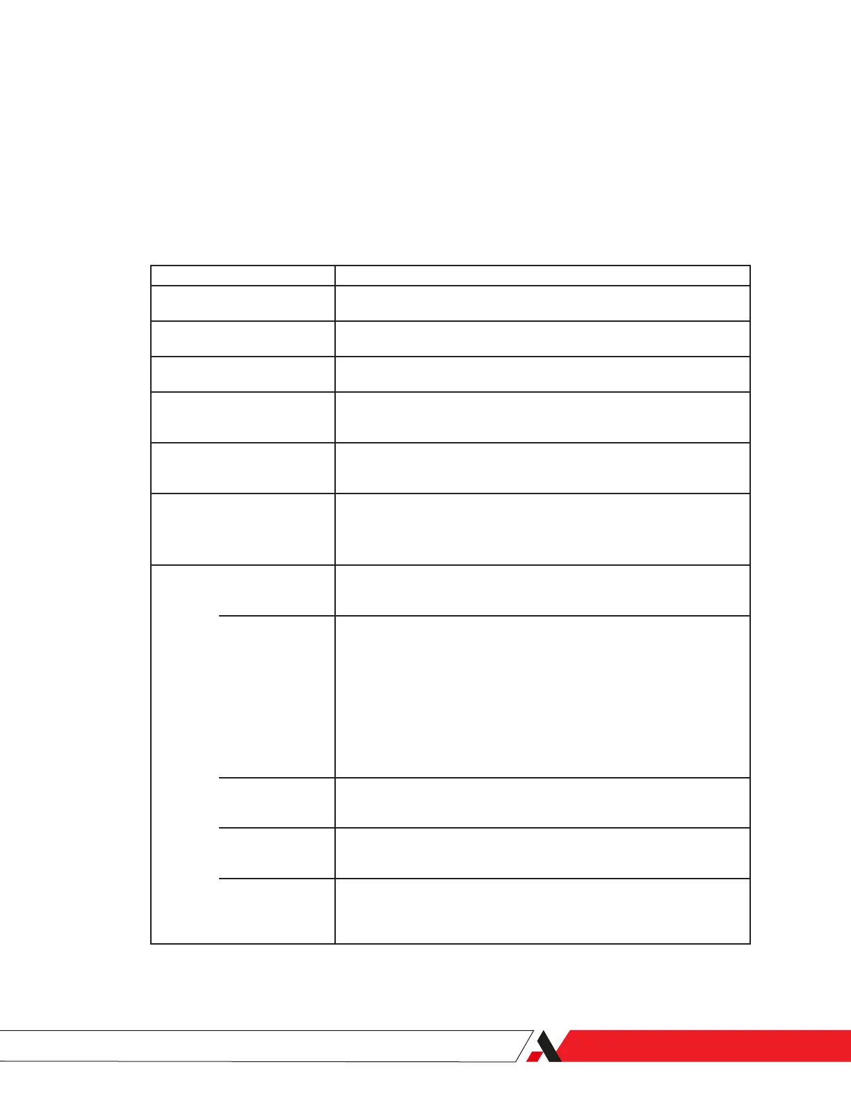
The sample system consists of:
Component Function
Sample Probe Extends into the process gas line to obtain a representative sample. Contains
an Isolation Valve to isolate the sample system from the process gas line.
Sample Line Transports the sample gas to the analyzer at a temperature above its dew-
point.
Check Valve Prevents gas ow reversal in the Filterblock if the sample pressure drops sud-
denly. This will prevent damage to the Membrane Filters.
Filterblock Assembly The Filterblock Assembly contains two (2) Membrane Filters and a coalescing
lter. Each lter stage has its own Flow Restrictor to provide liquid drainage
and a fast loop to the common Vent Line.
Flow Restrictor Flow restrictors control the ow rate of the sample gas and balance any pres-
sure drops within the sample system and Measuring Cell. Never operate the
analyzer without the Flow Restrictors in place.
Flame Arrestor Fittings One ame arrestor connects the analyzer to a dry “purge” gas supply (typically
N2) via the Cooler Housing.
Two (2) ame arrestors are used on the Measuring Cell for the gas Sample
Inlet and Outlet.
Measuring Cell The Measuring Cell contains the mirrors, LEDs, phototransistors, Thermo-
electric Cooler (TEC), resistive temperature device (RTD) used to measure the
sample gas. These and other Cell components include:
Mirror The integral element is the mirror, which has two planed surfaces that are
exposed to the sample gas inside the Measuring Cell. One of these surfaces is
a rough, black surface used to detect hydrocarbon condensation. The other is
a polished, reective surface used to detect water condensation.
The placement of the mirror surfaces at the top of the gas sample chamber al-
lows excess liquid formed on the mirror to fall away from the light paths. This
prevents the build-up of liquids on the mirror surfaces. Any liquid that falls
from the mirror and doesn’t vaporize upon contacting the warmer Measur-
ing Cell wall is swept from the Measuring Cell during the Purging/Hold Stage
through the sample outlet located at the bottom of the Measuring Cell.
RTD Located within the mirror, near the two planed surfaces, is a resistance tem-
perature device (RTD) which is used by the Microcontroller board to monitor
and control mirror temperature.
Mirror Support The mirror is mounted in a plastic support plate that has good mechanical
strength for containing the pressurized sample gas and has poor thermal
conductivity for thermally isolating the mirror.
TEC Assembly The lower surface of the Thermoelectric Cooler (TEC) Assembly is in close
thermal contact with the upper surface of the mirror. The upper surface of
the Cooler Assembly is in close thermal contact with the lower surface of the
Heatsink.
Overview | 1-7

 Loading...


