PN 903-8797, Rev A
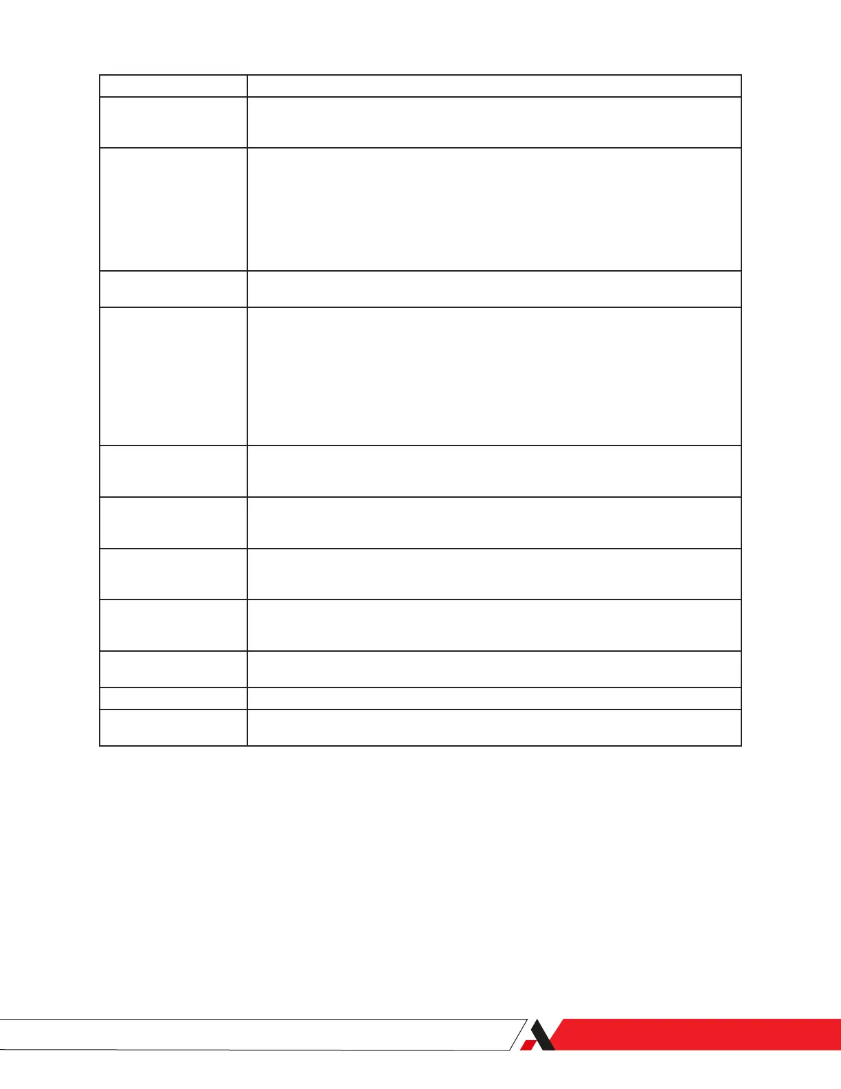
Sub-Menu Item Description
Tz This system status parameter (T) indicates the Run-Time (Days Hours:Minutes – 000 00:00) at
the beginning of the Cooling Stage for each of the last nine measuring cycles (where ‘z’ = 1–9:
‘1’ = most recent entry and ‘9’ = oldest entry).
^WDz This history buer displays the Water Dewpoint temperature (°C or °F) for the last nine
measuring cycles (where ‘z’ = 1–9: ‘1’ = most recent entry and ‘9’ = oldest entry).
Note:
This signal will be displayed only if an external water signal is provided and if the
H2O DP:EXT option is enabled from the MonitorCFG menu. If the H2O DP:INT
option is enabled, the WDP readings are derived from the internal water mirror
surface – not recommended.
^HCDz This history buer displays the Hydrocarbon Dewpoint temperature (°C or °F) for the last nine
measuring cycles (where ‘z’ = 1–9: ‘1’ = most recent entry and ‘9’ = oldest entry).
^WCz This history buer displays the external Water Content (optional, if used) in mg/m
3
, lb/MMcf,
PPMV, or PPMW values for the last nine measuring cycles (where ‘z’ = 1–9: ‘1’ = most recent
entry and ‘9’ = oldest entry).
Note:
This signal will be displayed only if an external water signal is provided and if the
H2O CT:EXT option is enabled from the MonitorCFG menu. If the H2O DP:INT
(with water content) option is enabled, these readings are derived from the
internal water mirror surface – not recommended
^WMirz n This history buer displays the phototransistor signal from the Water-side of the mirror at
the start of the Run cycle, for the last nine measuring cycles (where ‘z’ = 1–9: ‘1’ = most recent
entry and ‘9’ = oldest entry, and where ‘n’ = the displayed phototransistor signal value).
^HCMirz n This history buer displays the phototransistor signal from the Hydrocarbon-side of the mirror
at the start of the Run cycle, for the last nine measuring cycles (where ‘z’ = 1–9: ‘1’ = most
recent entry and ‘9’ = oldest entry, and where ‘n’ = the displayed phototransistor signal value).
^SCz n This history buer displays the basic Status Code alarms for the last nine measuring cycles
(where ‘z’ = 1–9: ‘1’ = most recent entry and ‘9’ = oldest entry, and where ‘n’ = the total sum of
all primary SCode alarms triggered during the last measuring cycle).
^XSCz n This history buer displays the basic Extended Status Code alarms for the last nine measuring
cycles (where ‘z’ = 1–9: ‘1’ = most recent entry and ‘9’ = oldest entry, and where ‘n’ = the total
sum of all primary XSCode alarms triggered during the last measuring cycle).
EEP WR n This system status parameter displays the number of writes (‘n’ = total number of writes) to
the analyzer’s EEPROM (changes to the system conguration settings).
000000000-1 This system status parameter displays the Serial Number of the analyzer.
M241 Vx-xx This system status parameter displays the current Firmware Version running the 241CE II
Analyzer.
User Interface | 3-13

 Loading...


