PN 305200901, Rev YT
Electrical Connections
1. Remove terminal cover.
2. Connect the 4–20 mA analog output and alarm contacts from the analyzer
to user recording equipment (Figures 2-5 and 2-6).
3. Connect RS-232 or RS-485 serial communication from analyzer to the PC
being used for customer parameter setup (Figures 2-7 through 2-9).
4. Insert the RS-485 termination plug into the RS-485 out connection if
communicating with one analyzer or the last in a chain (Figure 2-8).
5. Connect 24 VDC power to analyzer.
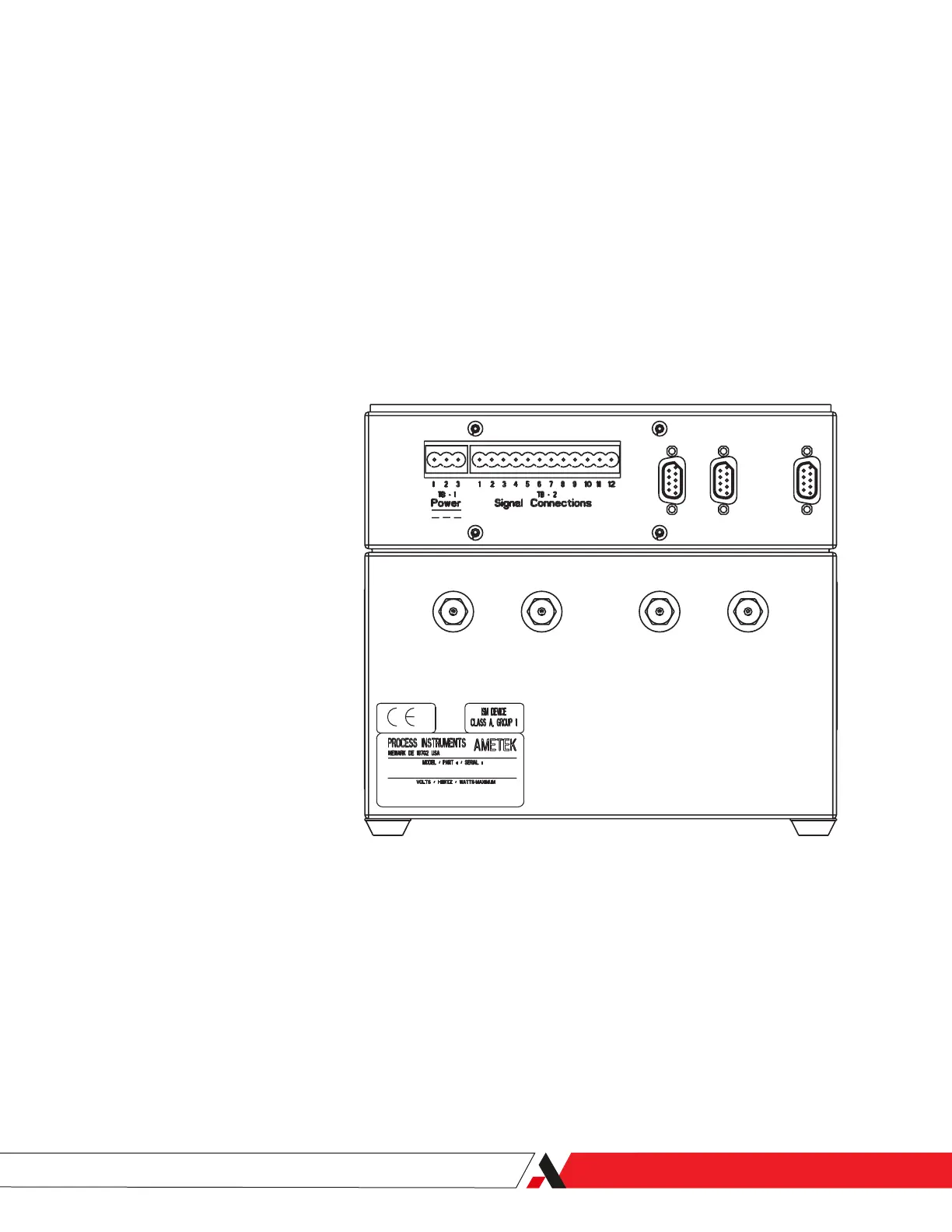
Figure 2-5.
3050-OLV Power and Signal
Connections, Rear View.
Power
Terminal Function
1 DC P ower , 24 +/- 4 Volts 3.15 Amps Fused
2 DC Common
3 Chassis Ground
Signal Connections
Terminal Function
1 Remote Pressure Transmitter +
2 Remote Pressure Transmitter Return
3 4-20 mA Output Source
4 Isolated 24V po wer supply +, 50 mA maximum
5 Isolated 24V pow er supply -
6 4-20 mA Output Return
7 System Alarm Relay
8 System Alarm Relay
9 Concentration Alarm Relay
10Concentration Alarm Relay
11
Data Valid Relay
12
Data Valid Relay
3050-OLV Connections
Rear View
RS-232
RS-485 In
RS-485 Out
Out
Exhaust
50 PSI Max
In
Sample
Dryer
To
Dryer
From
Installation and Start-Up | 2-11

 Loading...


