PN 305200901, Rev YT
Flow Checks
The 3050-OLV-SLR, -TE, and -DO analyzer black boxes all have an internal
Plumbing diagram (Figure 4-7).
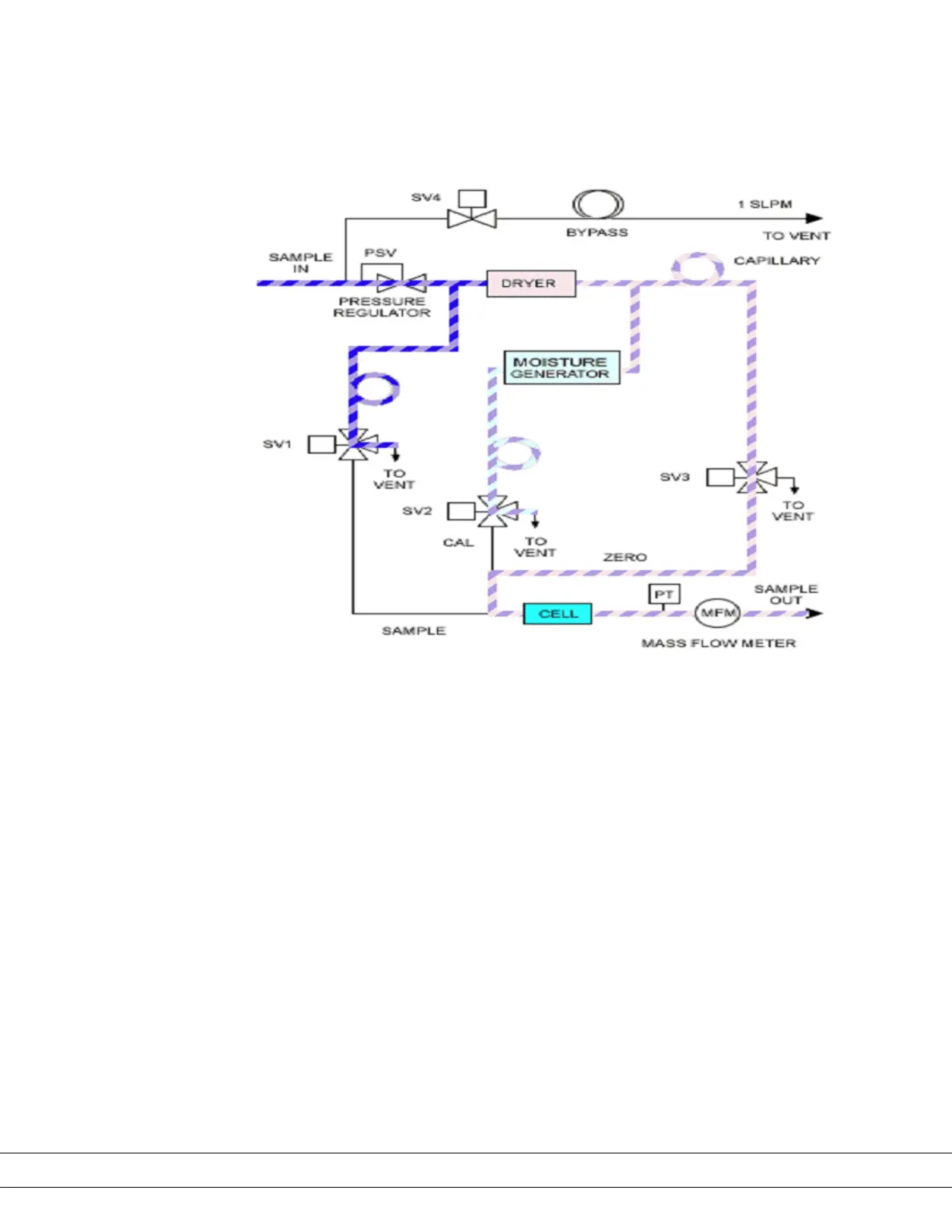
Figure 4-7.
3050-OLV Internal Plumbing
Diagram.
Note that there is one common input, Sample In, and one common output,
Sample Out. All four vents from the valves are tied to the sample out vent.
Although this diagram is simplied, visualize that all vents are tied to this
common vent. The ow through the detector is controlled by the inlet PSV
(Proportional valve), which in turn is controlled by the MCU board. The MCU
board reads the ow from the Mass Flow Meter (MFM) and in turn controls the
PSV valve to a set point of 50 SCCM, ±5 SCCM. At any given moment, there is
only one ow through the cell. Thus, since all ows are tied to the same vent, if
you place a ow meter on the common exhaust it should read a total ow very
close to 150 SCCM (50 SCCM, ±5 SCCM per leg: Sample, Reference, and Moisture
Generator legs).
Note that the Bypass valve remained closed during this process. The Bypass
valve will increase ow by about approximately 1 liter/minute, ±100 SCCM. For
troubleshooting purposes, the Bypass valve should remain closed until the
ow problem is xed.
4-12 | 3050-OLV Moisture Analyzer

 Loading...


