PN 305200901, Rev YT
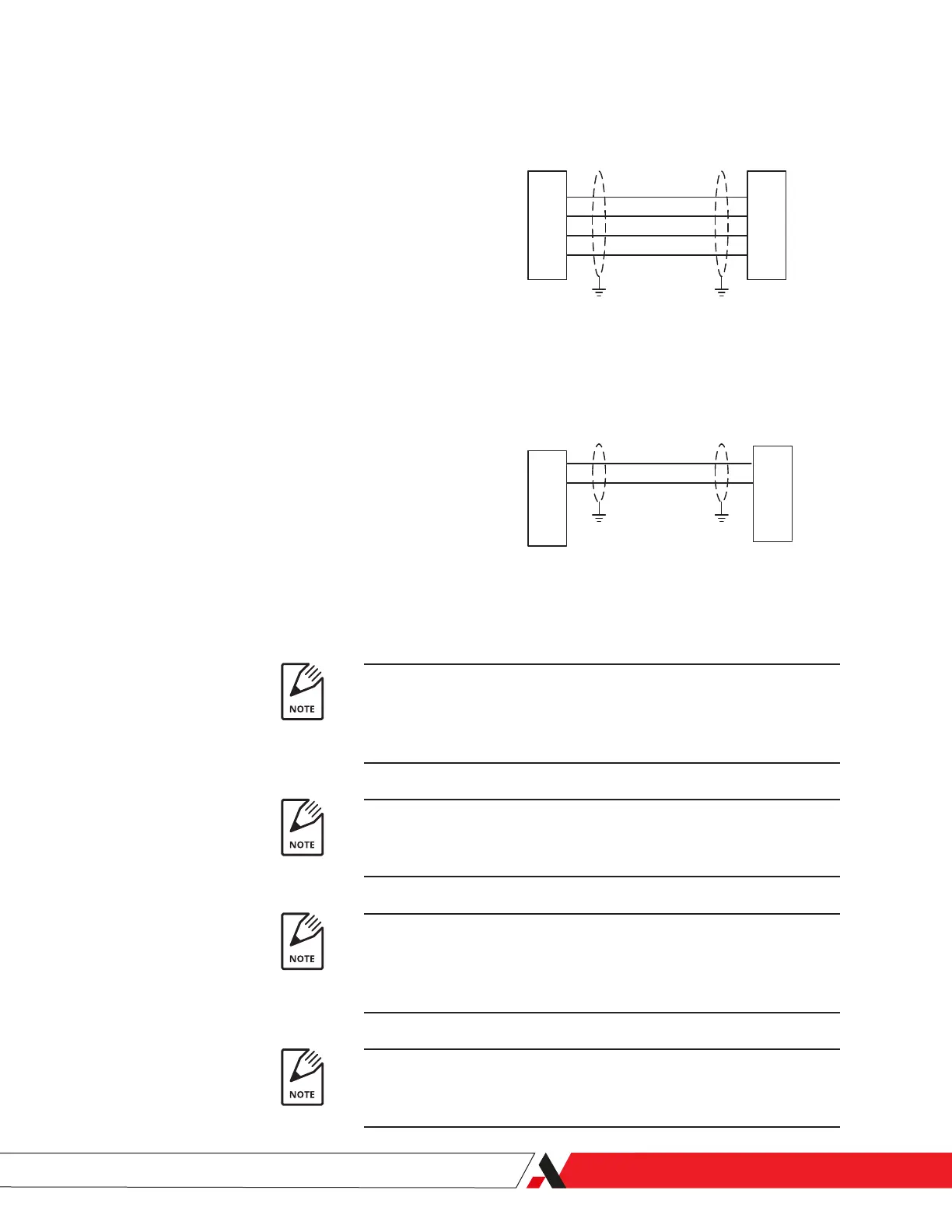
RS-485 Cables, Multiple 3050-OLV Analyzers
4
5
8
9
4
5
8
9
RS-485 OUT
3050-OLV
(type DB9M)
RS485 Cables, Multiple 3050-OLV's
4 wire
2 wire
4
5
4
5
RS-485 OUT
3050-OLV
(type DB9M)
RS-485 IN
3050-OLV
(type DB9M)
RS-485 IN
3050-OLV
(type DB9M)
Notes
1. Total cable length not to exceed 1000m. Cable should be low capacitance type for use in
RS-485 applications (nominal impedance of 120 Ohms, shielded twisted pairs).
For example Belden 9841 in two wire applications, Belden 9842 in 4 wire applications.
2. Install terminator plug (p/n 305 900 901) in RS485 OUT position of last controller
in
networks with both single and multiple 3050-OLV's.
3. Cable shields should be connected to both the analyzer and the DCS. If this is not
possible, cable shields should be tied to the chassis at each 3050-OLV. If this is not
possible, tie the shield at the PC or DCS to chassis and remaining shield to the chassis
through a 0.1 mF @ 500V capacitor
4. Adding a jumper between pins 1 and 3 disab les softw are control of the
RS-485 mode. With jumper installed, the 3050-OLV will always be in 4 wire mode.
Figure 2-8.
RS-485 Cables,
Multiple 3050-OLV Analyzers.
Total cable length not to exceed 1000 m. Cable should be low capaci-
tance type for use in RS-485 applications (nominal impedance of 120
ohms, shielded twisted pairs). For example Belden 9841 in 2-wire ap-
plications, Belden 9842 in 4-wire applications.
Install terminator plug (PN 305900901) in RS-485 OUT position of last
controller in networks with both single and multiple 3050-OLV Analyz-
ers.
Cable shields should be connected to both the analyzer and the DCS.
If this is not possible, cable shields should be tied to the chassis at each
3050-OLV. If this is not possible, tie the shield at the PC or DCS to chassis
and remaining shield to the chassis through a 0.1 mF @ 500 V capacitor.
Adding a jumper between Pins ‘1’ and ‘3’ disables software control of
the RS-485 mode. With a jumper installed, the 3050-OLV will always be
in 4-wire mode.
Installation and Start-Up | 2-15

 Loading...


